
Hardware IO 16 8 1

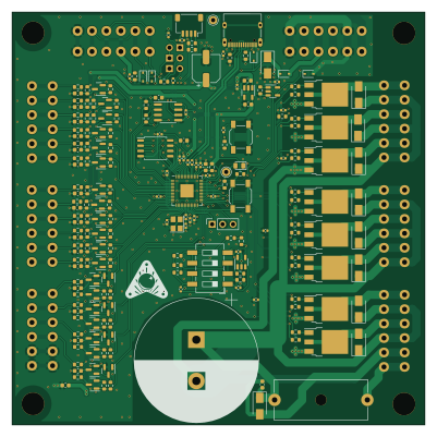
About the Hardware IO 16 8 1 PCB
Hardware IO 16 8 1 is an open source RP2040/RP2350 PCB design by PPUC, published on GitHub under the TAPR-OHL-1.0 license. It is a 2-layer board measuring 100 × 100 mm, with 217 components from 46 distinct parts.
Its main chip is the RP2040, from the RP2040/RP2350 family. Other key parts include the ADM3483, W25Q128JVSIQ, LMV321, SN74AHCT1G125 and AP2112K-3.3. By type, the board carries 97 resistors, 49 capacitors, 32 transistors, 16 diodes, 9 connectors and 6 ICs.
From the project
Hardware for the generic I/O Board for PPUC
All inputs can also be used as signal-outputs (if programmed accordingly). The output is internally pulled up by a 10k resistor to 5 V. A higher voltage can be applied externally (max. 30 V) but be sure to have your hardware and software! setup correctly as no protection for damage is provided in that case. A maximum of 2 mA can be sinked/sourced.
The inputs In2 and In3 are designed for higher speed (100 kHz). The Pull-Up can be soldered to other pads to be pulled to 3,3 V (instead of 5 V). An input capacitance can be added (soldered) for better noise immunity but lower speed. Since version…
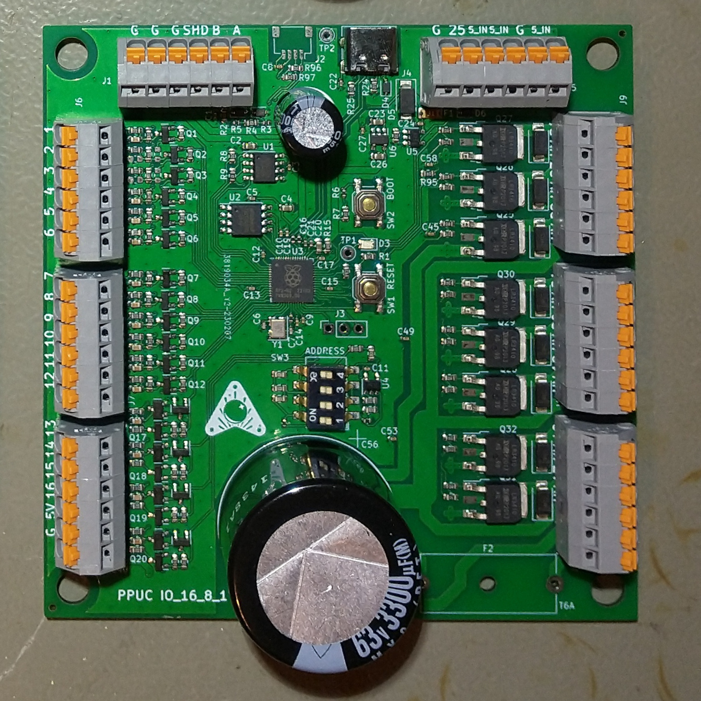
Main components on the Hardware IO 16 8 1
Hardware IO 16 8 1 bill of materials (BOM)
217 components, 46 distinct parts — part numbers from the project's BOM.
| Qty | Part | Footprint | Refs |
|---|---|---|---|
| 1 | ADM3483 | SOIC-8_3.9x4.9mm_P1.27mm | U1 |
| 1 | W25Q128JVSIQ | SOIC-8_5.23x5.23mm_P1.27mm | U2 |
| 1 | RP2040 | QFN-56-1EP_7x7mm_P0.4mm_EP3.2x3.2mm | U3 |
| 1 | LMV321 | SOT-23-5 | U4 |
| 1 | SN74AHCT1G125 | SOT-23-5 | U5 |
| 1 | AP2112K-3.3 | SOT-23-5 | U6 |
| 20 | 2N7002 | SOT-23 | Q1, Q2, Q3, Q4, Q5, Q6, Q7, Q8 +12 |
| 4 | AO3400A | SOT-23 | Q13, Q14, Q15, Q16 |
| 8 | NCE0140KA | TO-252-3_TabPin4 | Q25, Q26, Q27, Q28, Q29, Q30, Q31, Q32 |
| 1 | C9002 12MHz,18pF | Crystal_SMD_3225-4Pin_3.2x2.5mm | Y1 |
| 8 | Conn_01x06 | Terminal_Block_RTMPin | J1, J5, J6, J7, J8, J9, J10, J11 |
| 1 | USB_C_RECEPTACLE_USB2.0 USB_C_Receptacle_USB2.0 | USB_C_Receptacle_XKB_U262-16XN-4BVC11 | J4 |
| 1 | T6A | Fuseholder_Cylinder-5x20mm_Schurter_0031_8201_Horizontal_Open | F2 |
| 3 | Jumper_2_Open | PinHeader_1x02_P2.54mm_Vertical | JP1, JP2, JP3 |
| 1 | C318884 Reset | SW_SPST_SKQG_WithStem | SW1 |
| 1 | C318884 Boot | SW_SPST_SKQG_WithStem | SW2 |
| 1 | C54950 ADDRESS | SW_DIP_SPSTx04_Slide_6.7x11.72mm_W8.61mm_P2.54mm_LowProfile | SW3 |
| 2 | SD15 | D_SOD-323 | D1, D2 |
| 1 | C2297 LED gn | LED_0805_2012Metric | D3 |
| 2 | C191023 1A | D_SOD-323 | D4, D16 |
Show 26 more
| Qty | Part | Footprint | Refs |
|---|---|---|---|
| 1 | SMAJ5.0 | D_SMA | D5 |
| 1 | SD05 | D_SOD-323 | D6 |
| 8 | MRA4004T3G | D_SMA | D7, D8, D9, D10, D11, D12, D13, D14 |
| 1 | SMAJ60 | D_SMA | D15 |
| 20 | 100N 100n | C_0402_1005Metric | C1, C3, C5, C8, C9, C10, C11, C12 +12 |
| 6 | 10U 10u | C_0603_1608Metric | C2, C4, C20, C23, C26, C40 |
| 2 | 27PF 27pF | C_0402_1005Metric | C6, C7 |
| 2 | 1u | C_0402_1005Metric | C16, C21 |
| 1 | C37308 100µ 16V | CP_Elec_6.3x5.4 | C25 |
| 16 | 470P 470p | C_0603_1608Metric | C28, C29, C30, C31, C32, C33, C34, C35 +8 |
| 1 | 3300µ 63V | CP_Radial_D30.0mm_P10.00mm_SnapIn | C56 |
| 1 | C14663 100n 50V | C_0603_1608Metric | C57 |
| 46 | 10K 10k | R_0603_1608Metric | R1, R7, R8, R26, R33, R36, R37, R38 +38 |
| 11 | 100R | R_0603_1608Metric | R2, R15, R82, R83, R84, R88, R89, R90 +3 |
| 2 | 620 | R_0402_1005Metric | R3, R5 |
| 1 | 120R | R_0603_1608Metric | R4 |
| 4 | 1k | R_0402_1005Metric | R6, R12, R16, R20 |
| 1 | 0 | R_0603_1608Metric | R9 |
| 2 | 27 | R_0402_1005Metric | R10, R11 |
| 1 | 33K 33k | R_0603_1608Metric | R13 |
| 4 | 2k | R_0603_1608Metric | R14, R18, R19, R23 |
| 1 | 5k | R_0603_1608Metric | R17 |
| 1 | 470 | R_0603_1608Metric | R21 |
| 5 | 3k | R_0603_1608Metric | R22, R34, R35, R40, R41 |
| 2 | 5K1 5k1 | R_0603_1608Metric | R24, R25 |
| 16 | 330 | R_0603_1608Metric | R27, R28, R29, R30, R31, R32, R45, R46 +8 |
Hardware IO 16 8 1 design files
The KiCad project lives in the PPUC/Hardware_IO_16_8_1 repository on GitHub; these links point at the commit this page was built from.
Hardware IO 16 8 1: common questions
What microcontroller does the Hardware IO 16 8 1 use?
The Hardware IO 16 8 1 is built around the RP2040, from the RP2040/RP2350 family.
How big is the Hardware IO 16 8 1 PCB?
The Hardware IO 16 8 1 measures 100 × 100 mm, has 2 copper layers and is 1.6 mm thick.
How many components are on the Hardware IO 16 8 1?
217 components, from 46 distinct parts, with part numbers taken from the project's own BOM. The full bill of materials is listed on this page.
Where can I download the Hardware IO 16 8 1 design files?
From the PPUC/Hardware_IO_16_8_1 repository on GitHub, which has the KiCad layout, the schematic and the BOM; the links under Design files point to each one.
Can I use the Hardware IO 16 8 1 design in my own project?
Yes, under the terms of its TAPR-OHL-1.0 license, which PPUC chose for the repository.
Can I test firmware for the Hardware IO 16 8 1 without the hardware?
Yes. HardLabs builds a simulation of the board from its netlist and BOM, so you can run and debug RP2040/RP2350 firmware against it before you order a PCB.
Similar boards
 RP2040/RP2350
Open Book Abridged Edition
joeycastillo
85 × 115 mm29 parts2LCC-BY-SA-4.08.1k RP2040/RP2350
Corne
foostan
277.2 × 107.5 mm164 parts2LCC-BY-4.07.7k RP2040/RP2350
Corne
277.2 × 107.5 mm164 parts2LCC-BY-4.07.7k RP2040/RP2350
Msa
Mentra-Community
47.8 × 9.4 mm53 parts2LMIT1.2k RP2040/RP2350
Open Source Smart Glasses
93 × 10.5 mm80 parts4LMIT1.2k RP2040/RP2350
MSA
30.5 × 138 mm61 parts2LMIT1.2k