
Dual Converter Motherboard

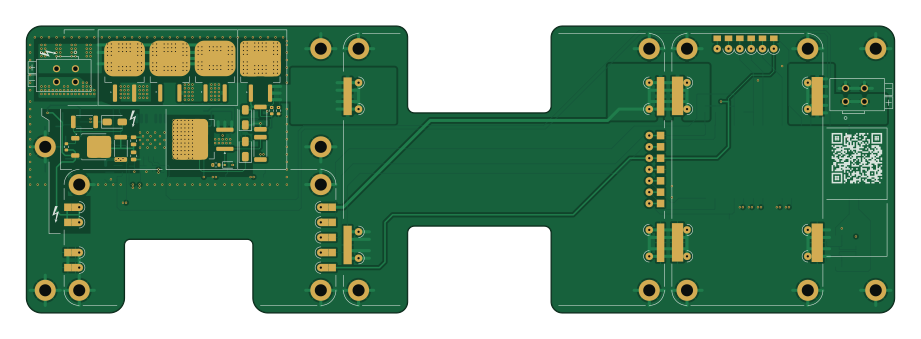
About the Dual Converter Motherboard PCB
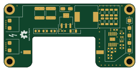
Dual Converter Motherboard is an open source PCB design by Rack-Robotics, published on GitHub. It is a 6-layer board measuring 230 × 76 mm, with 67 components from 31 distinct parts.
Other key parts include the POWER_MANAGEMENT_MODULE, HIGH-CURRENT_PHASE_MODULE_V1.0, HIGH-VOLTAGE_PHASE_MODULE, UCC23313BDWYR and TMCS1133C1A. By type, the board carries 29 resistors, 13 capacitors, 10 diodes, 8 ICs, 3 transistors and 3 connectors.
It belongs with the power & battery and sensors designs in this gallery.
From the project
electrical-discharge power supply, open-source
A high-efficiency power supply unit designed for Electrical Discharge Machining (EDM) applications.
- circuit-boards/ - KiCAD PCB designs for all modules - schematics/ - Schematic PDFs for electronics - KiCAD-library/ - Custom component library and 3D models - LTSpice/ - Simulation files - powercoreV3-firmware/ - Arduino firmware for the RP2040 controller
- PSU HIGHLIGHTS - FEATURES - APPLICATIONS - GENERAL DESCRIPTION - SPECIFICATIONS - Recommended Operating Conditions - DEVICE INTERFACES - Power Input Connector - Power Output Connector - Digital Interface Connector - USB-Micro Serial…
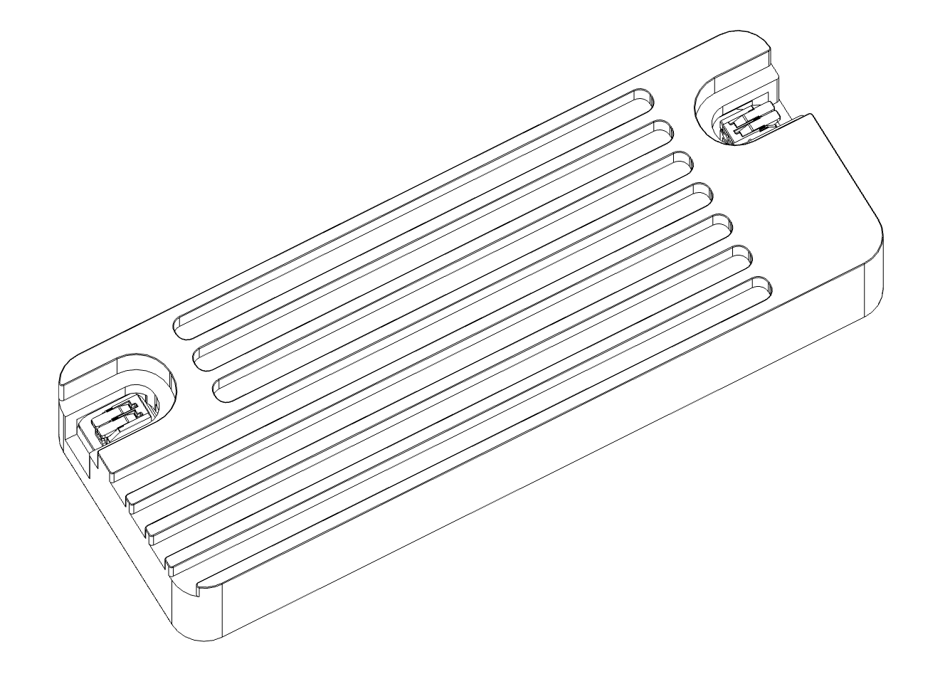
Main components on the Dual Converter Motherboard
Dual Converter Motherboard bill of materials (BOM)
67 components, 31 distinct parts — part numbers from the project's BOM.
| Qty | Part | Footprint | Refs |
|---|---|---|---|
| 1 | POWER_MANAGEMENT_MODULE | POWER_MANAGEMENT_MODULE_FOOTPRINT_V1.0 | U1 |
| 1 | HIGH-CURRENT_PHASE_MODULE_V1.0 | HIGH-CURRENT_PHASE_MODULE_FOOTPRINT_V1.0 | U2 |
| 1 | HIGH-VOLTAGE_PHASE_MODULE | HIGH-VOLTAGE_PHASE_MODULE_FOOTPRINT_V1.0 | U3 |
| 3 | UCC23313BDWYR Texas Instruments | UCC23313BDWYR | U4, U6, U7 |
| 1 | TMCS1133C1A Texas Instruments | TMCS1133C3AQDVGR | U5 |
| 1 | SC0915 Raspberry Pi | SC0915 | U8 |
| 1 | SUM110P08-11L-E3 Vishay Siliconix | SUM110P08-11L-E3 | Q1 |
| 1 | DMP45H4D9HK3-13 Vishay Siliconix | DMP45H4D9HK3-13 | Q2 |
| 1 | SIHB068N60EF-GE3 Vishay Siliconix | TO-263-2 | Q3 |
| 2 | 2601-1102 WAGO Corporation | 2601-1102 | J1, J2 |
| 1 | S4B-XH-SM4-TB JST Sales America Inc. | S4B-XH-SM4-TB | J3 |
| 3 | US1M-13-F Diodes Incorporated | D_SMA | D1, D2, D8 |
| 3 | STPSC20065GY STPSC20065GY-TR STMicroelectronics | STPSC20065GY-TR | D3, D4, D5 |
| 3 | C110525 D_Zener Diodes Incorporated | D_SMA | D6, D7, D10 |
| 1 | C82043 D_Zener onsemi | D_SOD-323 | D9 |
| 1 | BBUP00100505330Y00 Murata Electronics | L_0402_1005Metric | L1 |
| 6 | 220 nF YAGEO | C_0603_1608Metric | C1, C6, C8, C9, C10, C13 |
| 4 | 10000 pF YAGEO | C_0603_1608Metric | C2, C14, C15, C16 |
| 1 | 10 nF TDK Corporation | C_0805_2012Metric | C3 |
| 1 | 0.47 uF YAGEO | C_0805_2012Metric | C7 |
Show 11 more
| Qty | Part | Footprint | Refs |
|---|---|---|---|
| 1 | 0.1 uF KEMET | C_1210_3225Metric | C11 |
| 2 | 1K YAGEO | R_0603_1608Metric | R1, R2 |
| 8 | 10K YAGEO | R_0603_1608Metric | R3, R4, R12, R14, R17, R20, R21, R25 |
| 2 | 255K YAGEO | R_0603_1608Metric | R5, R6 |
| 3 | 10R YAGEO | R_2512_6332Metric | R7, R9, R24 |
| 3 | 332K YAGEO | R_0805_2012Metric | R8, R10, R11 |
| 1 | C840599 1R Bourns Inc. | R_2512_6332Metric | R13 |
| 3 | 100R YAGEO | R_0603_1608Metric | R15, R19, R26 |
| 2 | 1K YAGEO | R_2512_6332Metric | R16, R27 |
| 3 | 2.2K YAGEO | R_0603_1608Metric | R18, R28, R29 |
| 2 | 12K TE Connectivity Passive Product | R_2512_6332Metric | R22, R23 |
Dual Converter Motherboard design files
The KiCad project lives in the Rack-Robotics/Powercore-V3 repository on GitHub; these links point at the commit this page was built from.
Dual Converter Motherboard: common questions
How big is the Dual Converter Motherboard PCB?
The Dual Converter Motherboard measures 230 × 76 mm, has 6 copper layers and is 1.6 mm thick.
How many components are on the Dual Converter Motherboard?
67 components, from 31 distinct parts, with part numbers taken from the project's own BOM. The full bill of materials is listed on this page.
Where can I download the Dual Converter Motherboard design files?
From the Rack-Robotics/Powercore-V3 repository on GitHub, which has the KiCad layout, the schematic and the BOM; the links under Design files point to each one.
Can I use the Dual Converter Motherboard design in my own project?
The repository has no license, so all rights stay with Rack-Robotics. Use it as a reference, and ask the author before reusing the design.
More boards in Powercore-V3
Similar boards
Sensor smd
scottbez1
40 × 20 mm5 parts2LApache-2.04.2k
Sensors
StuckAtPrototype
15.2 × 9 mm14 parts4LApache-2.03.8k
EinkPDA screen
TalismanDesign
95 × 54 mm27 parts2LApache-2.02.0k
Stack chan
stack-chan
50 × 50 mm33 parts2LApache-2.01.7k
Display Carrier
AxxAxx
35.6 × 58.2 mm5 parts2LGPL-3.01.7k
Microphone
Mentra-Community
5.5 × 6.1 mm6 parts2LMIT1.2k