
Rp2040-logic analyzer

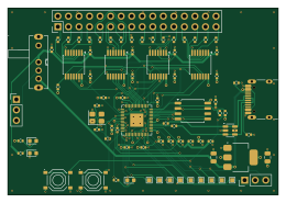
About the Rp2040-logic analyzer PCB
Rp2040-logic analyzer is an open source RP2040/RP2350 PCB design by ramtuc, published on GitHub under the CERN-OHL-P-2.0 license. It is a 4-layer board measuring 65 × 45 mm, with 73 components from 22 distinct parts.
Its main chip is the RP2040, from the RP2040/RP2350 family. Other key parts include the W25Q128JVSIQ, TXU0104PWR, AMS1117-3.3 and USBLC6-2SC6. By type, the board carries 27 capacitors, 27 resistors, 8 ICs, 4 connectors, 3 switches and 3 diodes.
It belongs with the test & measurement designs in this gallery.
From the project
RP2040 + TXU0104 16ch logic analyzer board for PulseView (sigrok-pico), 4-layer, JLCPCB PCBA
RP2040 と TI の TXU0104(レベル変換 ×4)で作った、16ch のロジックアナライザ基板です。1.8V〜5V のロジックをそのまま受け、sigrok-pico のファームを書くと PulseView(sigrok)から I2C・SPI・UART をデコードできます。4 層・65 × 45mm で、部品実装は JLCPCB の PCBA に任せています。
- A0 基板の検証は第3回(実戦投入)で一区切りです。 第2回で立ち上げ(3.3V レール 3.303V・水晶 12MHz・RP2040 内蔵 LDO 1.096V・PulseView で I2C をデコード)、第3回でしきい値・サンプリング上限・時間窓を実測し、SPI/UART/サーボ PWM をデコードしました。第3回の実測値(A0・SW1 改修済み・picodig26.uf2): - 1.8V ロジックは EXT で読めます。 VREF = 1.806V(EXT)で VT+ 1.399V/VT− 0.732V。雑音を抑えた入力で測り直した 3.3V 位置は VT+ 2.401V/VT− 1.395V、5V 位置は VT+ 3.290V/VT− 2.138V(0.05V 刻みの掃引)。VT+ は TXU0104 データシートの近い VCCA 行の上限より高めで、原因は未特定です -…
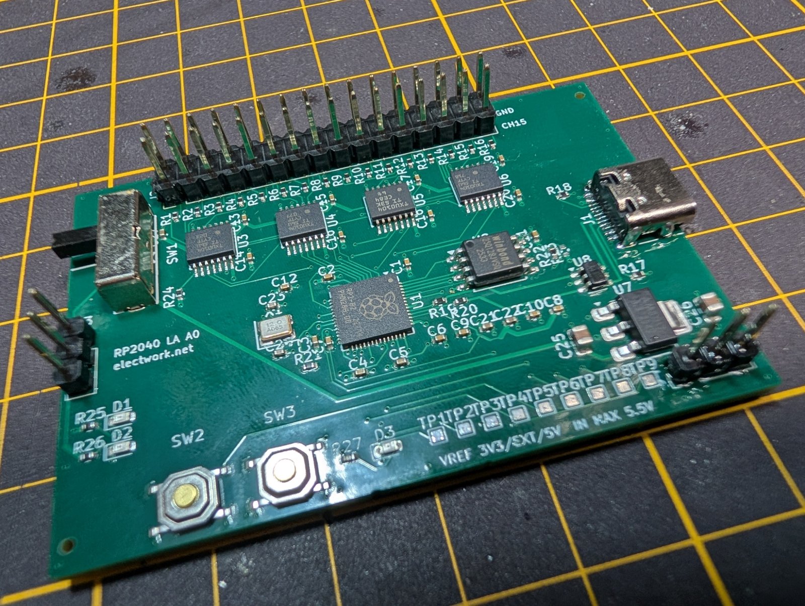
Main components on the Rp2040-logic analyzer
Rp2040-logic analyzer bill of materials (BOM)
73 components, 22 distinct parts — part numbers from the project's BOM.
| Qty | Part | Footprint | Refs |
|---|---|---|---|
| 1 | RP2040 | QFN-56-1EP_7x7mm_P0.4mm_EP3.2x3.2mm | U1 |
| 1 | W25Q128JVSIQ | SOIC-8_5.3x5.3mm_P1.27mm | U2 |
| 4 | TXU0104PWR | TSSOP-14_4.4x5mm_P0.65mm | U3, U4, U5, U6 |
| 1 | AMS1117-3.3 | SOT-223-3_TabPin2 | U7 |
| 1 | USBLC6-2SC6 | SOT-23-6 | U8 |
| 1 | C20625731 ABM8-272-T3 12MHz | Crystal_SMD_3225-4Pin_3.2x2.5mm | X1 |
| 1 | TYPE-C-31-M-12 | USB_C_Receptacle_HRO_TYPE-C-31-M-12 | J1 |
| 1 | PROBE 2x16 | PinHeader_2x16_P2.54mm_Vertical | J2 |
| 1 | VREF_EXT | PinHeader_1x03_P2.54mm_Vertical | J3 |
| 1 | ADC 1x3 (DNF) | PinHeader_1x03_P2.54mm_Vertical | J4 |
| 1 | SK13D07VG5 | SW-TH_SK13D07VG5 | SW1 |
| 2 | TS-1187A-B-A-B | SW-SMD_4P-L5.1-W5.1-P3.70-LS6.5-TL_H1.5 | SW2, SW3 |
| 3 | C2286 LED RED | LED_0603_1608Metric | D1, D2, D3 |
| 20 | 100NF 100nF | C_0402_1005Metric | C1, C2, C3, C4, C5, C6, C7, C8 +12 |
| 3 | 1µF | C_0402_1005Metric | C21, C22, C27 |
| 2 | 15PF 15pF | C_0402_1005Metric | C23, C24 |
| 2 | 10µF | C_0805_2012Metric | C25, C26 |
| 16 | 100Ω | R_0402_1005Metric | R1, R2, R3, R4, R5, R6, R7, R8 +8 |
| 2 | 5.1kΩ | R_0402_1005Metric | R17, R18 |
| 2 | 27Ω | R_0402_1005Metric | R19, R20 |
Show 2 more
| Qty | Part | Footprint | Refs |
|---|---|---|---|
| 5 | 1kΩ | R_0402_1005Metric | R21, R22, R25, R26, R27 |
| 2 | 10kΩ | R_0402_1005Metric | R23, R24 |
Rp2040-logic analyzer design files
The KiCad project lives in the ramtuc/rp2040-logic-analyzer repository on GitHub; these links point at the commit this page was built from.
Rp2040-logic analyzer: common questions
What microcontroller does the Rp2040-logic analyzer use?
The Rp2040-logic analyzer is built around the RP2040, from the RP2040/RP2350 family.
How big is the Rp2040-logic analyzer PCB?
The Rp2040-logic analyzer measures 65 × 45 mm, has 4 copper layers and is 1.6 mm thick.
How many components are on the Rp2040-logic analyzer?
73 components, from 22 distinct parts, with part numbers taken from the project's own BOM. The full bill of materials is listed on this page.
Where can I download the Rp2040-logic analyzer design files?
From the ramtuc/rp2040-logic-analyzer repository on GitHub, which has the KiCad layout, the schematic and the BOM; the links under Design files point to each one.
Can I use the Rp2040-logic analyzer design in my own project?
Yes, under the terms of its CERN-OHL-P-2.0 license, which ramtuc chose for the repository.
Can I test firmware for the Rp2040-logic analyzer without the hardware?
Yes. HardLabs builds a simulation of the board from its netlist and BOM, so you can run and debug RP2040/RP2350 firmware against it before you order a PCB.
More boards in rp2040-logic-analyzer
Similar boards
 RP2040/RP2350
Open Book Abridged Edition
joeycastillo
85 × 115 mm29 parts2LCC-BY-SA-4.08.1k RP2040/RP2350
Corne
foostan
277.2 × 107.5 mm164 parts2LCC-BY-4.07.7k RP2040/RP2350
Corne
277.2 × 107.5 mm164 parts2LCC-BY-4.07.7k RP2040/RP2350
LogicAnalyzer
gusmanb
57 × 55.2 mm6 parts2LGPL-3.05.0k RP2040/RP2350
Jitx design
55.5 × 65 mm26 parts4LGPL-3.05.0k RP2040/RP2350
Main
google
98 × 71 mm102 parts2LApache-2.02.9k