
Original

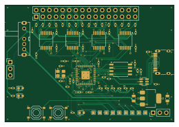
About the Original PCB
Original is an open source RP2040/RP2350 PCB design by ramtuc, published on GitHub under the CERN-OHL-P-2.0 license. It is a 4-layer board measuring 65 × 45 mm, with 73 components from 22 distinct parts.
Its main chip is the RP2040, from the RP2040/RP2350 family. Other key parts include the W25Q128JVSIQ, TXU0104PWR, AMS1117-3.3 and USBLC6-2SC6. By type, the board carries 27 capacitors, 27 resistors, 8 ICs, 4 connectors, 3 switches and 3 diodes.
It belongs with the test & measurement designs in this gallery.
From the project
RP2040 + TXU0104 16ch logic analyzer board for PulseView (sigrok-pico), 4-layer, JLCPCB PCBA
RP2040 と TI の TXU0104(レベル変換 ×4)で作った、16ch のロジックアナライザ基板です。1.8V〜5V のロジックをそのまま受け、sigrok-pico のファームを書くと PulseView(sigrok)から I2C・SPI・UART をデコードできます。4 層・65 × 45mm で、部品実装は JLCPCB の PCBA に任せています。
- A0 基板の検証は第3回(実戦投入)で一区切りです。 第2回で立ち上げ(3.3V レール 3.303V・水晶 12MHz・RP2040 内蔵 LDO 1.096V・PulseView で I2C をデコード)、第3回でしきい値・サンプリング上限・時間窓を実測し、SPI/UART/サーボ PWM をデコードしました。第3回の実測値(A0・SW1 改修済み・picodig26.uf2): - 1.8V ロジックは EXT で読めます。 VREF = 1.806V(EXT)で VT+ 1.399V/VT− 0.732V。雑音を抑えた入力で測り直した 3.3V 位置は VT+ 2.401V/VT− 1.395V、5V 位置は VT+ 3.290V/VT− 2.138V(0.05V 刻みの掃引)。VT+ は TXU0104 データシートの近い VCCA 行の上限より高めで、原因は未特定です -…
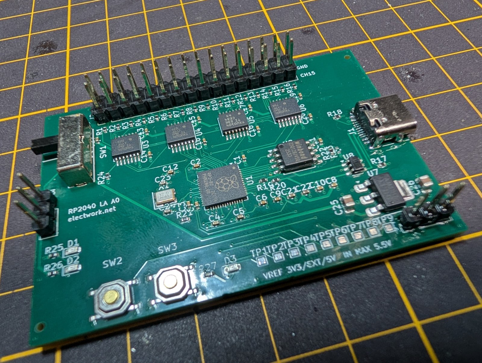
Main components on the Original
Original bill of materials (BOM)
73 components, 22 distinct parts — part numbers from the project's BOM.
| Qty | Part | Footprint | Refs |
|---|---|---|---|
| 1 | RP2040 | QFN-56-1EP_7x7mm_P0.4mm_EP3.2x3.2mm | U1 |
| 1 | W25Q128JVSIQ | SOIC-8_5.3x5.3mm_P1.27mm | U2 |
| 4 | TXU0104PWR | TSSOP-14_4.4x5mm_P0.65mm | U3, U4, U5, U6 |
| 1 | AMS1117-3.3 | SOT-223-3_TabPin2 | U7 |
| 1 | USBLC6-2SC6 | SOT-23-6 | U8 |
| 1 | C20625731 ABM8-272-T3 12MHz | Crystal_SMD_3225-4Pin_3.2x2.5mm | X1 |
| 1 | TYPE-C-31-M-12 | USB_C_Receptacle_HRO_TYPE-C-31-M-12 | J1 |
| 1 | PROBE 2x16 | PinHeader_2x16_P2.54mm_Vertical | J2 |
| 1 | VREF_EXT | PinHeader_1x03_P2.54mm_Vertical | J3 |
| 1 | ADC 1x3 (DNF) | PinHeader_1x03_P2.54mm_Vertical | J4 |
| 1 | SK13D07VG5 | SW-TH_SK13D07VG5 | SW1 |
| 2 | TS-1187A-B-A-B | SW-SMD_4P-L5.1-W5.1-P3.70-LS6.5-TL_H1.5 | SW2, SW3 |
| 3 | C2286 LED RED | LED_0603_1608Metric | D1, D2, D3 |
| 20 | 100NF 100nF | C_0402_1005Metric | C1, C2, C3, C4, C5, C6, C7, C8 +12 |
| 3 | 1µF | C_0402_1005Metric | C21, C22, C27 |
| 2 | 15PF 15pF | C_0402_1005Metric | C23, C24 |
| 2 | 10µF | C_0805_2012Metric | C25, C26 |
| 16 | 100Ω | R_0402_1005Metric | R1, R2, R3, R4, R5, R6, R7, R8 +8 |
| 2 | 5.1kΩ | R_0402_1005Metric | R17, R18 |
| 2 | 27Ω | R_0402_1005Metric | R19, R20 |
Show 2 more
| Qty | Part | Footprint | Refs |
|---|---|---|---|
| 5 | 1kΩ | R_0402_1005Metric | R21, R22, R25, R26, R27 |
| 2 | 10kΩ | R_0402_1005Metric | R23, R24 |
Original design files
The KiCad project lives in the ramtuc/rp2040-logic-analyzer repository on GitHub; these links point at the commit this page was built from.
Original: common questions
What microcontroller does the Original use?
The Original is built around the RP2040, from the RP2040/RP2350 family.
How big is the Original PCB?
The Original measures 65 × 45 mm, has 4 copper layers and is 1.6 mm thick.
How many components are on the Original?
73 components, from 22 distinct parts, with part numbers taken from the project's own BOM. The full bill of materials is listed on this page.
Where can I download the Original design files?
From the ramtuc/rp2040-logic-analyzer repository on GitHub, which has the KiCad layout, the schematic and the BOM; the links under Design files point to each one.
Can I use the Original design in my own project?
Yes, under the terms of its CERN-OHL-P-2.0 license, which ramtuc chose for the repository.
Can I test firmware for the Original without the hardware?
Yes. HardLabs builds a simulation of the board from its netlist and BOM, so you can run and debug RP2040/RP2350 firmware against it before you order a PCB.
More boards in rp2040-logic-analyzer
Similar boards
 RP2040/RP2350
Open Book Abridged Edition
joeycastillo
85 × 115 mm29 parts2LCC-BY-SA-4.08.1k RP2040/RP2350
Corne
foostan
277.2 × 107.5 mm164 parts2LCC-BY-4.07.7k RP2040/RP2350
Corne
277.2 × 107.5 mm164 parts2LCC-BY-4.07.7k RP2040/RP2350
LogicAnalyzer
gusmanb
57 × 55.2 mm6 parts2LGPL-3.05.0k RP2040/RP2350
Jitx design
55.5 × 65 mm26 parts4LGPL-3.05.0k RP2040/RP2350
Main
google
98 × 71 mm102 parts2LApache-2.02.9k