
H Bridge

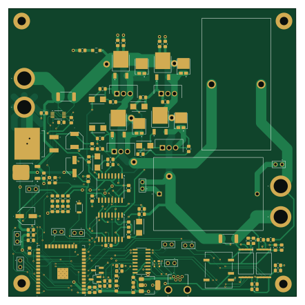
About the H Bridge PCB
H Bridge is an open source ESP32 PCB design by reinto1234, published on GitHub. It is a 2-layer board measuring 110.3 × 110.3 mm, with 120 components from 49 distinct parts.
Its main chip is the ATMEGA328P-PU, from the ESP32 family. Other key parts include the AMC1306M25DWVR, L7812ABD2T-TR, IR2110S, INA228 and LT1963AxST-3.3. By type, the board carries 36 capacitors, 30 resistors, 12 diodes, 11 connectors, 10 ICs and 10 transistors.
It belongs with the iot & wireless designs in this gallery.
From the project
- Input Voltage: 24 V - Input Current: up to 10 A - Power: ≈ 240 W
- Input Voltage: 24 V - Input Current: up to 10 A - Power: ≈ 240 W
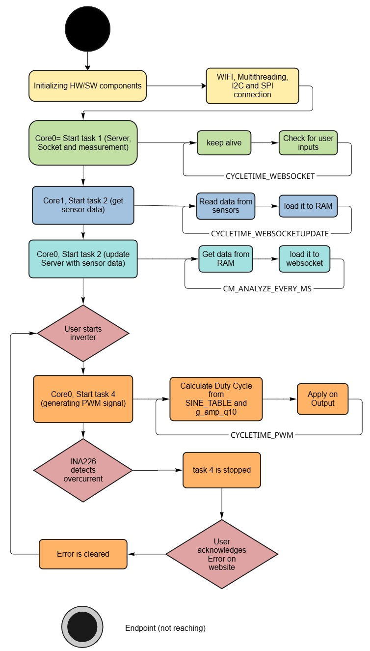
The project consists of two main components: 1. HBridgePCBDesign — KiCad PCB layout and schematic. 2. HBridgePCBCode — Firmware for the ESP32 controller.
Functions: - Start/Stop the inverter - Set VRMS target - Display live telemetry (Vin, Iin, VRMS, IRMS, PF, P, Q, f) - View and acknowledge overcurrent faults
Main components on the H Bridge
H Bridge bill of materials (BOM)
120 components, 49 distinct parts — part numbers from the project's BOM.
| Qty | Part | Footprint | Refs |
|---|---|---|---|
| 2 | AMC1306M25DWVR | SOIC127P1150X280-8N | IC1, IC3 |
| 1 | L7812ABD2T-TR | L7812ABD2TTR | IC2 |
| 1 | ATMEGA328P-PU ESP32-WROOM-32 | ESP32-WROOM-32 | U1 |
| 2 | IR2110S | SOIC-16W_7.5x10.3mm_P1.27mm | U2, U3 |
| 1 | INA228 | VSSOP-10_3x3mm_P0.5mm | U4 |
| 1 | LT1963AxST-3.3 | SOT-223-3_TabPin2 | U5 |
| 1 | LD1086DT50TR | TO-252-2 | U6 |
| 1 | CH340C | SOIC-16_3.9x9.9mm_P1.27mm | U7 |
| 4 | IRLB4030PBF | TO254P483X1016X1994-3P | Q1, Q2, Q3, Q4 |
| 4 | IPD90N10S4L06ATMA1 | IPD90N10S4L06ATMA1 | Q5, Q6, Q9, Q10 |
| 2 | BC817 | SOT-23_Handsoldering | Q7, Q8 |
| 10 | TSW-102-15-T-S | TSW-102-XX-YY-S | J1, J2, J3, J4, J5, J7, J9, J12 +2 |
| 1 | 1734510-1 | 17345101 | J13 |
| 1 | PHBC24N-2R0A0219V | PHBC24N2R0A0219V | FL1 |
| 1 | NXJ1S0303MC-R13 | NXJ1S0303MCR13 | PS1 |
| 1 | B3U-1000P | B3U-1000P | S1 |
| 4 | 575-4 | 5754 | TP1, TP2, TP3, TP4 |
| 2 | TLMG1100-GS15 TLMG1100-GS15-1 | R_0805_2012Metric_Pad1.20x1.40mm_HandSolder | LED1, LED4 |
| 1 | TLMG1100-GS15 TLMG1100-GS15-2 | R_0805_2012Metric_Pad1.20x1.40mm_HandSolder | LED2 |
| 1 | TLMG1100-GS15 TLMG1100-GS15-3 | R_0805_2012Metric_Pad1.20x1.40mm_HandSolder | LED3 |
Show 29 more
| Qty | Part | Footprint | Refs |
|---|---|---|---|
| 4 | FSV2060L | FSV2060L | D1, D2, D3, D5 |
| 1 | SP0503BAHT | SOT-143 | D4 |
| 6 | S210 | DIOM5336X265N | D6, D7, D8, D9, D10, D11 |
| 1 | HPZR-C26X | HPZRC26X | D12 |
| 1 | 100UF 2.2 uF | R_0805_2012Metric_Pad1.20x1.40mm_HandSolder | C1 |
| 2 | 220 nF | R_0805_2012Metric_Pad1.20x1.40mm_HandSolder | C2, C4 |
| 2 | 22 nF | R_0805_2012Metric_Pad1.20x1.40mm_HandSolder | C3, C5 |
| 1 | 2.2 uF | R_0805_2012Metric_Pad1.20x1.40mm_HandSolder | C6 |
| 3 | 100uF | EEE1AA101SP | C7, C8, C23 |
| 10 | 100 nF | R_0805_2012Metric_Pad1.20x1.40mm_HandSolder | C9, C10, C13, C18, C19, C22, C24, C30 +2 |
| 6 | 1µF | R_0805_2012Metric_Pad1.20x1.40mm_HandSolder | C11, C17, C21, C25, C26, C27 |
| 5 | 1 µF | R_0805_2012Metric_Pad1.20x1.40mm_HandSolder | C12, C31, C32, C34, C36 |
| 2 | 220nF | R_0805_2012Metric_Pad1.20x1.40mm_HandSolder | C14, C15 |
| 1 | B32776E4406J000 | B32776E4406J000 | C16 |
| 1 | 4.7 µF | R_0805_2012Metric_Pad1.20x1.40mm_HandSolder | C20 |
| 2 | 1 uF | R_0805_2012Metric_Pad1.20x1.40mm_HandSolder | C28, C29 |
| 2 | 2.2 | R_0805_2012Metric_Pad1.20x1.40mm_HandSolder | R1, R10 |
| 4 | 10 | R_0805_2012Metric_Pad1.20x1.40mm_HandSolder | R2, R3, R8, R9 |
| 6 | 10k | R_0805_2012Metric_Pad1.20x1.40mm_HandSolder | R4, R7, R30, R31, R40, R41 |
| 2 | 15K 10k | R_0805_2012Metric_Pad1.20x1.40mm_HandSolder | R5, R6 |
| 2 | 100 | R_0805_2012Metric_Pad1.20x1.40mm_HandSolder | R11, R27 |
| 1 | 1 | R_0805_2012Metric_Pad1.20x1.40mm_HandSolder | R12 |
| 2 | 12k | R_0805_2012Metric_Pad1.20x1.40mm_HandSolder | R13, R18 |
| 1 | 5k | R_0805_2012Metric_Pad1.20x1.40mm_HandSolder | R14 |
| 2 | GMR100HTBFER015 | R_2512_6332Metric_Pad1.40x3.35mm_HandSolder | R15, R42 |
| 1 | 120k | R_0805_2012Metric_Pad1.20x1.40mm_HandSolder | R16 |
| 2 | 1k | R_0805_2012Metric_Pad1.20x1.40mm_HandSolder | R17, R28 |
| 4 | 0 | R_0805_2012Metric_Pad1.20x1.40mm_HandSolder | R19, R20, R23, R24 |
| 1 | 330 | R_0805_2012Metric_Pad1.20x1.40mm_HandSolder | R29 |
H Bridge design files
The KiCad project lives in the reinto1234/H_Bridge_PCB repository on GitHub; these links point at the commit this page was built from.
H Bridge: common questions
What microcontroller does the H Bridge use?
The H Bridge is built around the ATMEGA328P-PU, from the ESP32 family.
How big is the H Bridge PCB?
The H Bridge measures 110.3 × 110.3 mm, has 2 copper layers and is 1.6 mm thick.
How many components are on the H Bridge?
120 components, from 49 distinct parts, with part numbers taken from the project's own BOM. The full bill of materials is listed on this page.
Where can I download the H Bridge design files?
From the reinto1234/H_Bridge_PCB repository on GitHub, which has the KiCad layout, the schematic and the BOM; the links under Design files point to each one.
Can I use the H Bridge design in my own project?
The repository has no license, so all rights stay with reinto1234. Use it as a reference, and ask the author before reusing the design.
Can I test firmware for the H Bridge without the hardware?
Yes. HardLabs builds a simulation of the board from its netlist and BOM, so you can run and debug ESP32 firmware against it before you order a PCB.
Similar boards
 ESP32
OSO-BOOK-B1
joeycastillo
85 × 115 mm65 parts2LCC-BY-SA-4.08.1k ESP32
Powertrain
byrantech
64 × 45.4 mm171 parts4LMIT4.3k ESP32
Esp32 minimal
atopile
36.2 × 26.8 mm20 parts2LMIT4.0k ESP32
Badge
56.3 × 39 mm239 parts4LMIT4.0k ESP32
Racer
StuckAtPrototype
36 × 50.2 mm70 parts4LApache-2.03.8k ESP32
Controller
29 × 74 mm58 parts4LApache-2.03.8k