
30 open source boards using the INA228
Real designs built with the INA228, from public GitHub projects: a quick way to see how others power, decouple and connect it. Each board comes with its KiCad files, full parts list and a render — and you can simulate its firmware on HardLabs.
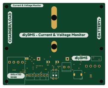 AVR/Arduino
DiyBMS-CurrentShunt
stuartpittaway
90 × 72 mm45 parts2LCC-BY-NC-4.060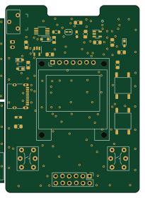 ESP32
Current logger
hnz1102
50 × 70 mm64 parts2LNo license18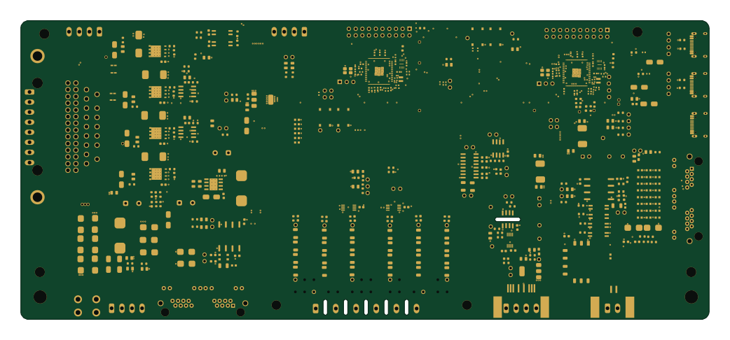 RP2040/RP2350
CellKeeper
cellkeeper-bms
260 × 113 mm405 parts4LGPL-3.011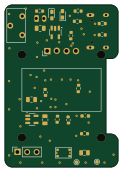 ESP32
Mini current meter
30 × 43 mm38 parts2LNo license10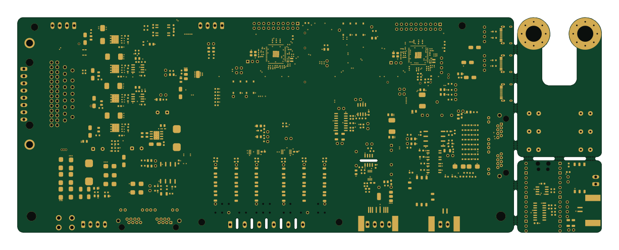 RP2040/RP2350
CellKeeper-BMS
clowrey
306 × 113 mm423 parts4LGPL-3.09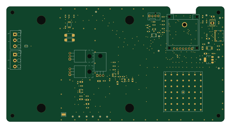 ESP32
Electricload
185 × 98 mm71 parts2LNo license5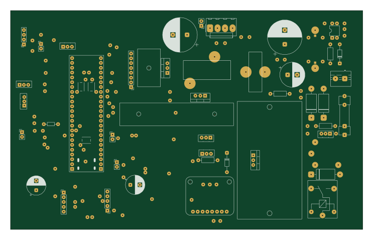
STM32G474-Precision-Lab-Power-Supply
Aleksei327
185.5 × 115.3 mm204 parts2LCC-BY-NC-4.04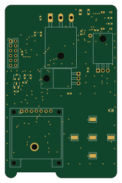 ESP32
Dcpower
58 × 90 mm101 parts2LNo license1 RISC-V
Hardware
openvalence
58 × 58 mm273 parts6LCERN-OHL-S-2.00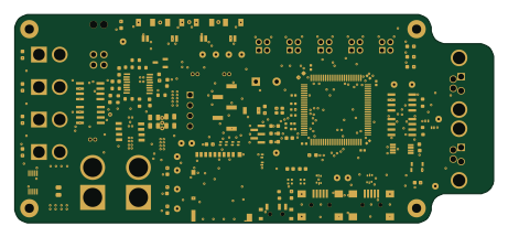 STM32
PROMETHEUS
EPFLRocketTeam
115 × 50 mm259 parts4LNo license0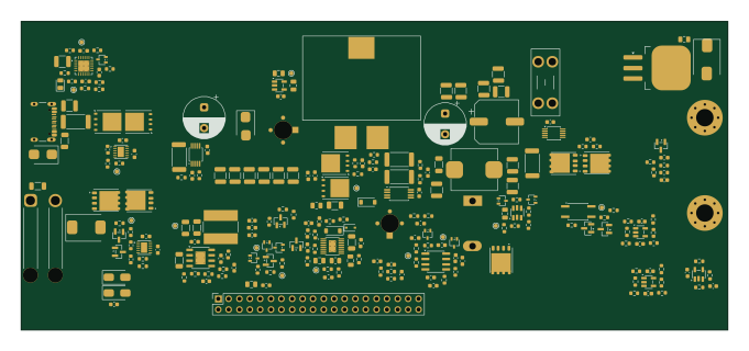
USB-C PD bench supply - power board
GarryBGoode
170 × 74.5 mm237 parts4LNo license0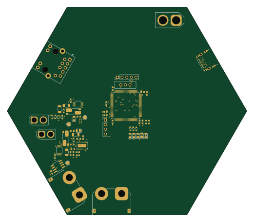 STM32
PDB
CalebJM04
130 × 112.6 mm227 parts6LNo license0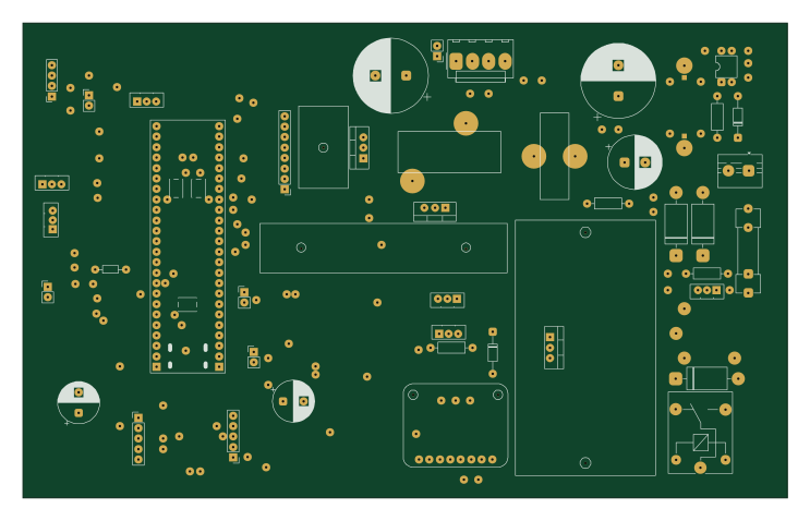
STM32G474-Precision-Lab-Power-Supply
nikunjmalik306
185.5 × 115.3 mm204 parts2LNo license0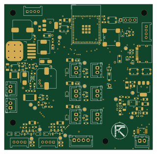 ESP32
Car iot services
karuru6225
80 × 78 mm131 parts2LNo license0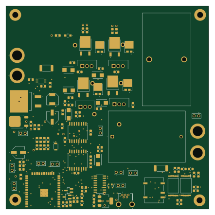 ESP32
H Bridge
reinto1234
110.3 × 110.3 mm120 parts2LNo license0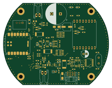 RP2040/RP2350
PowerControlModule
tokai-student-rocket-project
90 × 70 mm80 parts2LNo license0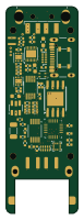 STM32
UsbMeter
TheBadZhang
17.5 × 50 mm68 parts4LNo license0 RP2040/RP2350
TRELLIS MC MCU Controller
twade12
100 × 80 mm45 parts2LNo license0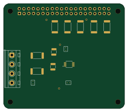
INA228-RPi hat
StefanoSchubert
65 × 56.5 mm12 parts2LNo license0- schematic only · 4 partsAVR/Arduino
Lifepo4-battery monitor
JoeyBobbles
4 partsMIT0 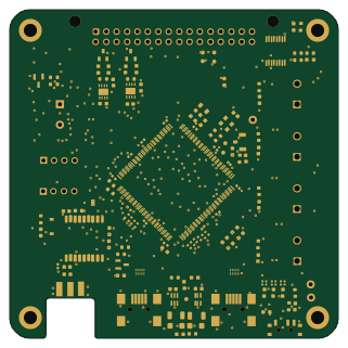 STM32
FH2 Flight Computer
80 × 80 mm245 parts4LNo license0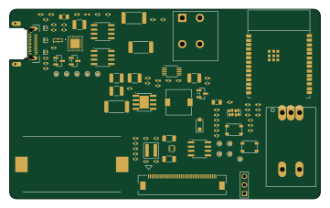 ESP32
Zone syntax test
gokcesena53
90 × 55 mm89 parts4LMIT0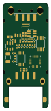 STM32
UsbMeter2
17.5 × 40.3 mm40 parts2LNo license0 STM32
Inference servers
embeddedos-org
420 × 300 mm637 parts16LMIT8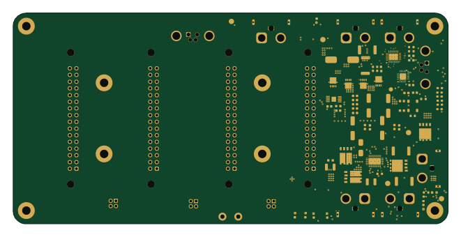
2026 C AV SPINE
165 × 80 mm172 parts4LNo license0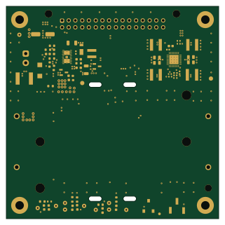
2026 C AV LPSU "ALASTOR"
80 × 80 mm114 parts4LNo license0 STM32
Rad tolerant electronics
233 × 220 mm547 parts16LMIT8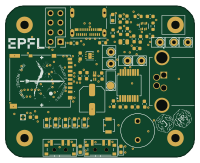 STM32
Flight Data Recorder
50 × 40 mm89 parts4LNo license0 STM32
Hardware security modules
300 × 200 mm510 parts16LMIT8 STM32
Npu subsystems
120 × 90 mm460 parts14LMIT8
How designs wire the INA228
Read from the KiCad layouts of 18 open source designs, one per repository: what each pin of the INA228 connects to, and the resistors, capacitors and other passives placed on it.
- The SCL pin has a pull-up to 3.3V on 14 of 18 designs, most often 10 kΩ (then 4.7 kΩ).
- The VS pin has a decoupling capacitor on 14 of 18 designs, most often 100 nF (then 10 µF).
- The SDA pin has a pull-up to 3.3V on 13 of 18 designs, most often 10 kΩ (then 4.7 kΩ).
- The VIN+ pin has a series resistor on 12 of 17 designs, most often 10 mΩ (then 5 mΩ).
| Pin | Connected to | Parts on the pin |
|---|---|---|
| A1pin 1 | Connected to: GND 75% · a signal 19% | — |
| A0pin 2 | Connected to: GND 75% · a signal 19% | — |
| ALERTpin 3 | Connected to: The microcontroller 50% · not connected 28% |
|
| SDApin 4 | Connected to: The microcontroller 56%, a connector 28% |
|
| SCLpin 5 | Connected to: The microcontroller 44%, a connector 28% |
|
| VSpin 6 | Connected to: 3.3V 83% · a signal 17% |
|
| GNDpin 7 | Connected to: GND 83% | — |
| VBUSpin 8 | Connected to: A connector 56% · VBUS_INA 22% |
|
| VIN-pin 9 | Connected to: A connector 47% |
|
| VIN+pin 10 | Connected to: A connector 41% |
|
Connections count pins, parts count designs; values in brackets are how many parts had that value. Designs read include DiyBMS-CurrentShunt by stuartpittaway, Current logger by hnz1102, CellKeeper by cellkeeper-bms and Mini current meter by hnz1102.
The INA228 in open source designs
The gallery holds 30 open source boards using the INA228 from 22 GitHub repositories; a typical one measures about 100 × 80 mm and carries around 126 components.
55% use four copper layers or more, and 30% carry an open source license.
The most starred is DiyBMS-CurrentShunt by stuartpittaway.
Parts used alongside the INA228
Microcontrollers on boards using the INA228
What boards using the INA228 are built for
INA228: common questions
Where can I find a INA228 reference design?
Each of the 30 boards on this page is a real design using the INA228. Open one to see how it is wired up, with the full BOM, a render of the layout and links to its KiCad files.
What pull-up resistor is used on the INA228 SCL pin?
The SCL pin has a pull-up to 3.3V on 14 of 18 designs, most often 10 kΩ (then 4.7 kΩ). Counted from the KiCad layouts of 18 open source designs using the INA228.
What decoupling capacitors do designs use on the INA228 VS pin?
The VS pin has a decoupling capacitor on 14 of 18 designs, most often 100 nF (then 10 µF). Counted from the KiCad layouts of 18 open source designs using the INA228.
What pull-up resistor is used on the INA228 SDA pin?
The SDA pin has a pull-up to 3.3V on 13 of 18 designs, most often 10 kΩ (then 4.7 kΩ). Counted from the KiCad layouts of 18 open source designs using the INA228.
What parts are used alongside the INA228?
The SPX3819M5-L, SSD1331_DISPLAY, ADS1115, AM26LV32EIDR and AMS1117-3.3 appear in the most repositories here.
Which microcontrollers do boards using the INA228 use?
Most are built on STM32 (10), ESP32 (7), RP2040/RP2350 (4) and AVR/Arduino (2).
How big is a typical board using the INA228?
The median is 100 × 80 mm, and 45% are two-layer designs.
What is the most popular open source board using the INA228?
By GitHub stars, DiyBMS-CurrentShunt by stuartpittaway, with 60 stars.
Can I simulate one of these boards using the INA228 before building it?
Yes. HardLabs turns a board's netlist and BOM into a working simulation, so you can boot and test firmware against it with no hardware on your desk.