
Shotpuck panel

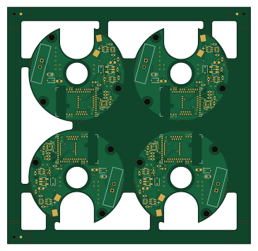
About the Shotpuck panel PCB
Shotpuck panel is an open source Nordic nRF PCB design by Rixard86, published on GitHub. It is a 2-layer board measuring 91 × 88.6 mm, with 108 components from 21 distinct parts.
Its main chip is the MDBT50Q-1MV2, from the Nordic nRF family. Other key parts include the LSM6DSO32TR, MCP73831T-2ACI/OT and BQ29700DSER. By type, the board carries 32 capacitors, 24 resistors, 16 ICs, 16 diodes, 8 transistors and 8 connectors.
It belongs with the power & battery, sensors and rf & radio designs in this gallery.
From the project
A Ø40 × 9.9 mm puck that bolts onto the free face of an Avalon riser weight (the weight's own 5/16-24 bolt, one size longer, goes through its centre), detects each shot with a 6-axis IMU, records the bow's motion around it (accelerometer + gyroscope, 1.0 s before to 0.5 s after r
A Ø40 × 9.9 mm puck that bolts onto the free face of an Avalon riser weight (the weight's own 5/16-24 bolt, one size longer, goes through its centre), detects each shot with a 6-axis IMU, records the bow's motion around it (accelerometer + gyroscope, 1.0 s before to 0.5 s after release), and reports both over BLE to the scoring app.
1. Magnetic connector: done: Samzo PR5L4015-2P-C-F from Electrokit (D18). For the charging cable, solder a 5 V lead to the male part (PR5L5015-2P-C-H) and check with a multimeter which pin meets the square pad (pin 1, +). A reversed lead cannot damage the puck…
Main components on the Shotpuck panel
Shotpuck panel bill of materials (BOM)
108 components, 21 distinct parts — part numbers from the project's BOM.
| Qty | Part | Footprint | Refs |
|---|---|---|---|
| 4 | MDBT50Q-1MV2 | Raytac_MDBT50Q | U1_0, U1_1, U1_2, U1_3 |
| 4 | LSM6DSO32TR | LGA-14_3x2.5mm_P0.5mm_LayoutBorder3x4y | U2_0, U2_1, U2_2, U2_3 |
| 4 | MCP73831T-2ACI/OT | SOT-23-5 | U3_0, U3_1, U3_2, U3_3 |
| 4 | BQ29700DSER | WSON-6_1.5x1.5mm_P0.5mm | U4_0, U4_1, U4_2, U4_3 |
| 4 | DMN63D8LDW | SOT-363_SC-70-6 | Q1_0, Q1_1, Q1_2, Q1_3 |
| 4 | DMN2004DWK | SOT-363_SC-70-6 | Q2_0, Q2_1, Q2_2, Q2_3 |
| 4 | Samzo PR5L4015-2P-C-F | MagPogo_Samzo_2P | J1_0, J1_1, J1_2, J1_3 |
| 4 | SWD pads | SWD_Pads_1x4_P2.54 | J2_0, J2_1, J2_2, J2_3 |
| 4 | LIR1254 (plain, spring contacts) | LIR1254_Contacts | BT1_0, BT1_1, BT1_2, BT1_3 |
| 8 | BAT54J | D_SOD-323F | D1_0, D1_1, D1_2, D1_3, D2_0, D2_1, D2_2, D2_3 |
| 4 | PESD5V0S1BB | D_SOD-523 | D3_0, D3_1, D3_2, D3_3 |
| 4 | LED green 0402 | LED_0402_1005Metric | D4_0, D4_1, D4_2, D4_3 |
| 8 | 4.7u 10V | C_0603_1608Metric | C1_0, C1_1, C1_2, C1_3, C2_0, C2_1, C2_2, C2_3 |
| 8 | 4.7u 6.3V | C_0402_1005Metric | C3_0, C3_1, C3_2, C3_3, C4_0, C4_1, C4_2, C4_3 |
| 16 | 100n | C_0402_1005Metric | C5_0, C5_1, C5_2, C5_3, C6_0, C6_1, C6_2, C6_3 +8 |
| 4 | 47k 1% | R_0402_1005Metric | R1_0, R1_1, R1_2, R1_3 |
| 4 | 1M | R_0402_1005Metric | R2_0, R2_1, R2_2, R2_3 |
| 4 | 100k | R_0402_1005Metric | R3_0, R3_1, R3_2, R3_3 |
| 4 | 1k | R_0402_1005Metric | R4_0, R4_1, R4_2, R4_3 |
| 4 | 330R | R_0402_1005Metric | R7_0, R7_1, R7_2, R7_3 |
Show 1 more
| Qty | Part | Footprint | Refs |
|---|---|---|---|
| 4 | 2.2k | R_0402_1005Metric | R8_0, R8_1, R8_2, R8_3 |
Shotpuck panel design files
The KiCad project lives in the Rixard86/shot-tracker repository on GitHub; these links point at the commit this page was built from.
Shotpuck panel: common questions
What microcontroller does the Shotpuck panel use?
The Shotpuck panel is built around the MDBT50Q-1MV2, from the Nordic nRF family.
How big is the Shotpuck panel PCB?
The Shotpuck panel measures 91 × 88.6 mm, has 2 copper layers and is 0.8 mm thick.
How many components are on the Shotpuck panel?
108 components, from 21 distinct parts, with part numbers taken from the project's own BOM. The full bill of materials is listed on this page.
Where can I download the Shotpuck panel design files?
From the Rixard86/shot-tracker repository on GitHub, which has the KiCad layout and the BOM; the links under Design files point to each one.
Can I use the Shotpuck panel design in my own project?
The repository has no license, so all rights stay with Rixard86. Use it as a reference, and ask the author before reusing the design.
Can I test firmware for the Shotpuck panel without the hardware?
Yes. HardLabs builds a simulation of the board from its netlist and BOM, so you can run and debug Nordic nRF firmware against it before you order a PCB.
More boards in shot-tracker
Similar boards
 Nordic nRF
TOTEM
GEIGEIGEIST
258.8 × 94.4 mm85 parts2LCERN-OHL-P-2.02.0k Nordic nRF
Pixl.js
solosky
40 × 23 mm45 parts4LGPL-2.01.4k Nordic nRF
Board
dennisss
363 × 128 mm420 parts4LApache-2.0381 Nordic nRF
Board hl15-latest
61 × 37 mm14 parts2LApache-2.0381 Nordic nRF
Management
101 × 31.5 mm50 parts2LApache-2.0381 Nordic nRF
Mikoto
zhiayang
18 × 33.3 mm53 parts4LApache-2.0355