
Diffpair test

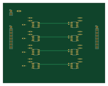
About the Diffpair test PCB
Diffpair test is an open source PCB design by rjwalters, published on GitHub under the MIT license. It is a 4-layer board measuring 90 × 70 mm, with 36 components from 10 distinct parts.
Other key parts include the SN65LVDS1DR and SN65LVDS2DR. By type, the board carries 17 capacitors, 8 ICs, 8 resistors and 3 connectors.
From the project
Standalone Python tools for parsing and manipulating KiCad schematic and PCB files
Four real SN65LVDS1 drivers send LVTTL header inputs over terminated LVDS pairs to SN65LVDS2 receivers and output headers. The board uses an explicitly reviewed four-layer JLC7628 construction, length-matched differential pairs, and ordinary through vias outside SMT lands.
See the assembled design guide for exact components, source regeneration, routing checks, fabrication settings and bench bring-up. The complete fabrication/assembly download is output/manufacturing.zip; current readiness is recorded in output/readiness.json. Three Samtec headers require manual through-hole assembly. No…
Main components on the Diffpair test
Diffpair test bill of materials (BOM)
36 components, 10 distinct parts — part numbers from the project's BOM.
| Qty | Part | Footprint | Refs |
|---|---|---|---|
| 4 | SN65LVDS1DR | SOIC-8_3.9x4.9mm_P1.27mm | U1, U3, U5, U7 |
| 4 | SN65LVDS2DR | SOIC-8_3.9x4.9mm_P1.27mm | U2, U4, U6, U8 |
| 1 | 3.3V regulated input | PinHeader_1x02_P2.54mm_Vertical | J1 |
| 1 | IN1-4 / GND | PinHeader_1x08_P2.54mm_Vertical | J2 |
| 1 | OUT1-4 / GND | PinHeader_1x08_P2.54mm_Vertical | J3 |
| 8 | 1NF 1nF | C_0603_1608Metric | C1, C3, C5, C7, C9, C11, C13, C15 |
| 8 | 100NF 100nF | C_0603_1608Metric | C2, C4, C6, C8, C10, C12, C14, C16 |
| 1 | 10UF 10uF | C_0805_2012Metric | C17 |
| 4 | 100 | R_0603_1608Metric | R1, R2, R3, R4 |
| 4 | 100K 100k | R_0603_1608Metric | R5, R6, R7, R8 |
Diffpair test design files
The KiCad project lives in the rjwalters/kicad-tools repository on GitHub; these links point at the commit this page was built from.
Diffpair test: common questions
How big is the Diffpair test PCB?
The Diffpair test measures 90 × 70 mm, has 4 copper layers and is 1.6 mm thick.
How many components are on the Diffpair test?
36 components, from 10 distinct parts, with part numbers taken from the project's own BOM. The full bill of materials is listed on this page.
Where can I download the Diffpair test design files?
From the rjwalters/kicad-tools repository on GitHub, which has the KiCad layout, the schematic and the BOM; the links under Design files point to each one.
Can I use the Diffpair test design in my own project?
Yes, under the terms of its MIT license, which rjwalters chose for the repository.
More boards in kicad-tools
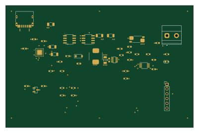
USB-C PD 5V supply — development
100 × 65 mm47 parts4LMIT74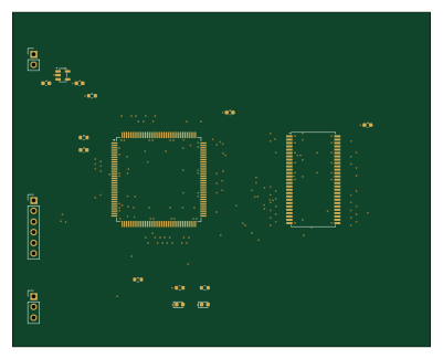 STM32
Matchgroup test routed
100 × 80 mm43 parts6LMIT74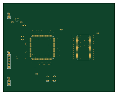 STM32
Matchgroup test
100 × 80 mm43 parts6LMIT74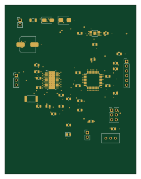 AVR/Arduino
Bldc controller routed
70 × 90 mm42 parts4LMIT74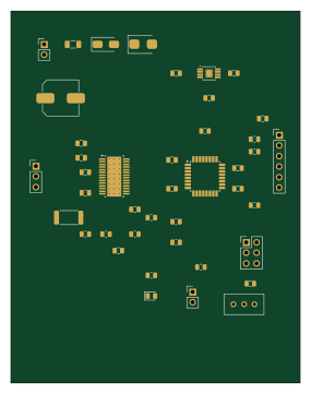 AVR/Arduino
Bldc controller
70 × 90 mm42 parts4LMIT74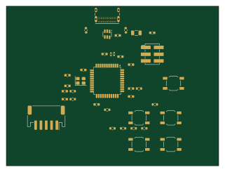 AVR/Arduino
Usb joystick
80 × 60 mm38 parts4LMIT74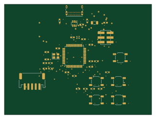 AVR/Arduino
Usb joystick routed
80 × 60 mm38 parts4LMIT74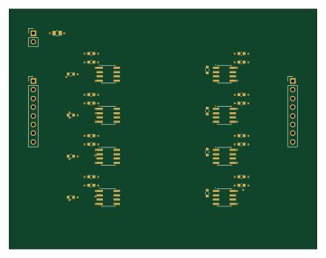
Diffpair test routed
90 × 70 mm36 parts4LMIT74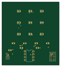 AVR/Arduino
Charlieplex 3x3 routed
50 × 55 mm19 parts2LMIT74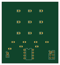 AVR/Arduino
Charlieplex 3x3
50 × 55 mm19 parts2LMIT74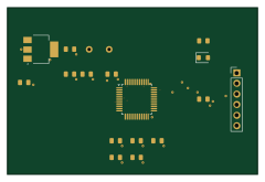 STM32
Stm32 devboard routed
60 × 40 mm17 parts2LMIT74