
Amplifier

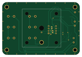
About the Amplifier PCB
Amplifier is an open source PCB design by RobertGawron, published on GitHub under the GPL-3.0 license. It is a 2-layer board measuring 79.8 × 55 mm, with 36 components from 16 distinct parts.
Other key parts include the LMC6062 and LM358. By type, the board carries 17 capacitors, 5 test points, 5 resistors, 3 battery holders, 2 ICs and 2 inductors.
It belongs with the science & space, audio and sensors designs in this gallery.
From the project
Nuclear radiation sensor with ionization chamber as a detector. Hard to make, IMHO inferior to semiconductor detectors.
There are many ionization chamber projects online, but most (though not all) produce false positive results. It's cool when a radioactive sample is placed near the detector and the detector shows an increased radiation value, but then, if you place your hand or any non-radioactive object nearby, the readings are high too. This is because, due to high amplification, these devices pick up a lot of noise, making the measurements unreliable.
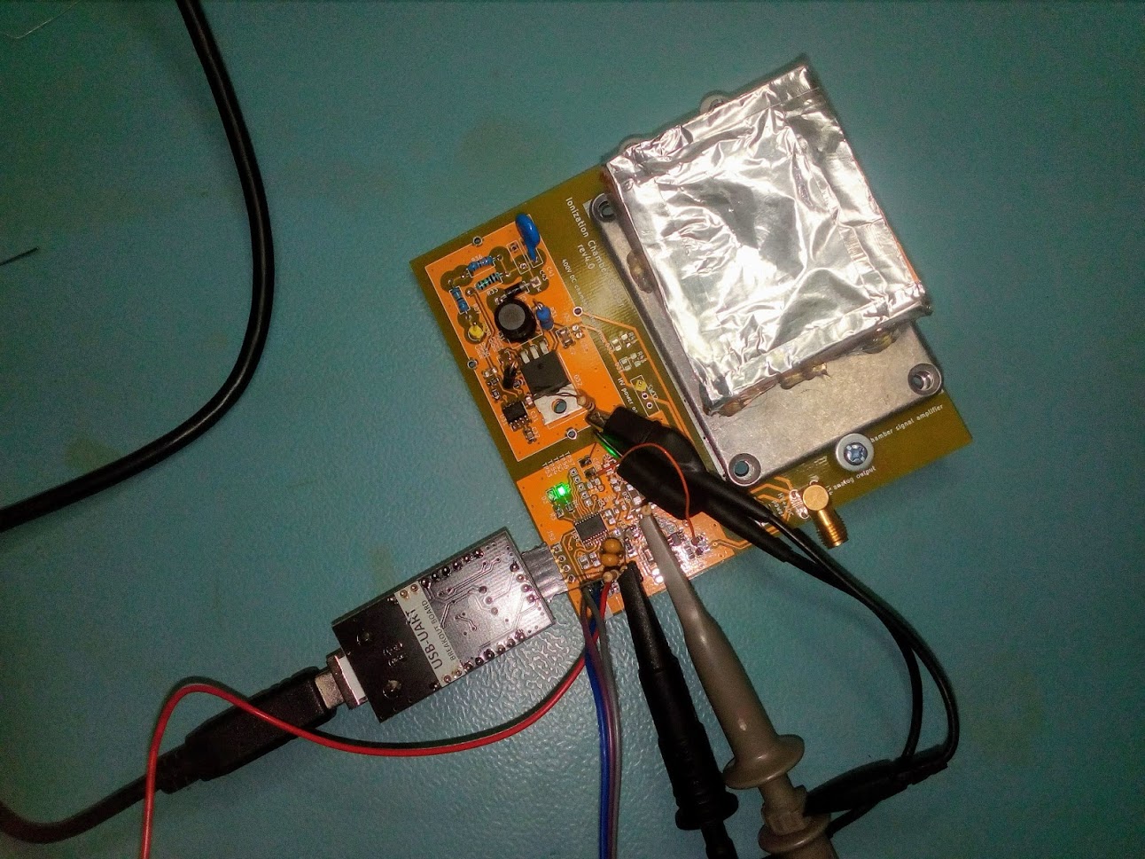
Main components on the Amplifier
Amplifier bill of materials (BOM)
36 components, 16 distinct parts.
| Qty | Part | Footprint | Refs |
|---|---|---|---|
| 1 | LMC6062 | DIP-8_W7.62mm | U1 |
| 1 | LM358 | SO-8_3.9x4.9mm_P1.27mm | U2 |
| 1 | RFShield_TwoPieces | IonizationChamberShield | J1 |
| 3 | Battery | AAAAPCBHolder | BT1, BT2, BT3 |
| 5 | TestPoint | TestPoint_Loop_D2.60mm_Drill0.9mm_Beaded | TP1, TP2, TP3, TP4, TP6 |
| 1 | Nuclear-Radiation_Detector | IonizationChamberSensor | V31 |
| 2 | 22u | L_7.3x7.3_H3.5 | L1, L2 |
| 5 | 100n | C_0805_2012Metric | C1, C40, C42, C44, C45 |
| 3 | 10n | C_0805_2012Metric | C2, C4, C5 |
| 4 | 1u | C_0805_2012Metric | C3, C7, C9, C10 |
| 2 | 100u/6v3 | CP_EIA-3528-21_Kemet-B | C6, C8 |
| 1 | not mounted | C_0805_2012Metric | C46 |
| 2 | 0R resistor | C_0805_2012Metric | C47, C48 |
| 1 | 2*50G | R_0805_2012Metric_Pad1.15x1.40mm_HandSolder | R38 |
| 2 | 10k | R_0805_2012Metric | R39, R41 |
| 2 | 120k | R_0805_2012Metric | R40, R42 |
Amplifier design files
The KiCad project lives in the RobertGawron/IonizationChamber repository on GitHub; these links point at the commit this page was built from.
Amplifier: common questions
How big is the Amplifier PCB?
The Amplifier measures 79.8 × 55 mm, has 2 copper layers and is 1.6 mm thick.
How many components are on the Amplifier?
36 components, from 16 distinct parts. The full bill of materials is listed on this page.
Where can I download the Amplifier design files?
From the RobertGawron/IonizationChamber repository on GitHub, which has the KiCad layout and the schematic; the links under Design files point to each one.
Can I use the Amplifier design in my own project?
Yes, under the terms of its GPL-3.0 license, which RobertGawron chose for the repository.
More boards in IonizationChamber
Similar boards

Sensor smd
scottbez1
40 × 20 mm5 parts2LApache-2.04.2k
Sensors
StuckAtPrototype
15.2 × 9 mm14 parts4LApache-2.03.8k
Microphone
Mentra-Community
5.5 × 6.1 mm6 parts2LMIT1.2k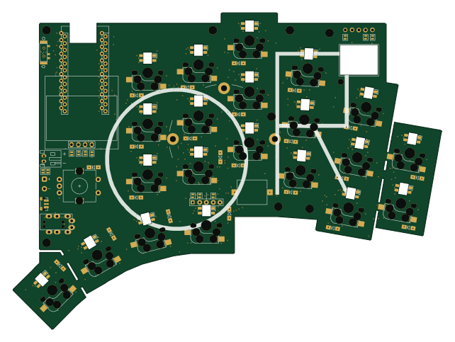
KLOR
GEIGEIGEIST
160.2 × 118.3 mm79 parts2LGPL-3.01.2k
TemperaturePCB PANEL
stuartpittaway
116 × 75.5 mm178 parts2LCC-BY-NC-4.01.1k
Pots
shanteacontrols
390 × 93 mm75 parts2LApache-2.0956