
LPC1758-MultiIOBoard

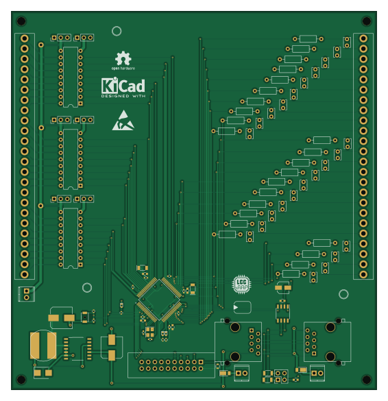
About the LPC1758-MultiIOBoard PCB
LPC1758-MultiIOBoard is an open source NXP PCB design by RobertPHeller, published on GitHub under the CC-BY-4.0 license. It is a 2-layer board measuring 141 × 146.1 mm, with 106 components from 40 distinct parts.
Its main chip is the LPC1758FBD80K, from the NXP family. Other key parts include the TCAN332DR, LM2574N-3.3 and TBD62X8X. By type, the board carries 45 capacitors, 31 resistors, 12 connectors, 6 ICs, 6 diodes and 2 transformers.
It belongs with the dev boards & breakouts designs in this gallery.
From the project
A collection of circuit designs for various MCUs, not just Raspberry Pis relating to Model Railroading
This is a collection of Model Railroad open hardware and open source projects, using LCC, OpenMRN, and OpenMRN-lite, for the following MCUs and SBCs:
Raspberry Pi, generally as HATs for the "B" flavors (RPi2B, RPi3B and RPi4B). (Directories with "HAT" at the end are for these boards.)
Beagle boards, including capes for BeagleBone Black and baseboards for PocketBeagles. (Directories with "CAPE" at the end are for BeagleBone Blacks, directories starting with "BBB" are also boards for the BeagleBone Black, directories starting with "PB" or "PocketBeagle" are for the PocketBeagles - these…
Main components on the LPC1758-MultiIOBoard
LPC1758-MultiIOBoard bill of materials (BOM)
106 components, 40 distinct parts.
| Qty | Part | Footprint | Refs |
|---|---|---|---|
| 1 | LPC1758FBD80K | QFP50P1400X1400X160-80N | U201 |
| 1 | TCAN332DR | SOIC-8_3.9x4.9mm_Pitch1.27mm | U301 |
| 1 | LM2574N-3.3 | SOIC-14_7.4x8.7mm_Pitch1.27mm | U401 |
| 3 | TBD62X8X | DIP-18_W7.62mm | U501, U502, U503 |
| 1 | 25MHZ | Crystal_SMD_Abracon_ABM8G-4pin_3.2x2.5mm | Y201 |
| 1 | ARM-20-JTAG | IDC_Header_Straight_20pins | J201 |
| 2 | RJ45 | RJ45_8N-S | J301, J302 |
| 1 | Outputs | Molex_KK_396_01x24_3.96mm_RightAngle | J501 |
| 1 | - PWD + | TerminalBlock_Pheonix_MPT-2.54mm_2pol | J502 |
| 3 | Sink Source | Pin_Header_Straight_1x03_Pitch2.54mm | J503, J504, J505 |
| 3 | Source Sink | Pin_Header_Straight_1x03_Pitch2.54mm | J506, J507, J508 |
| 1 | Inputs | Molex_KK_396_01x24_3.96mm_RightAngle | J601 |
| 1 | Termination | Pin_Header_Straight_2x02_Pitch2.54mm | JP301 |
| 1 | RESET | SW_SPST_B3U-1000P-B | SW201 |
| 1 | - 15 in + | TerminalBlock_Pheonix_MPT-2.54mm_2pol | T301 |
| 1 | - 15 out + | TerminalBlock_Pheonix_MPT-2.54mm_2pol | T302 |
| 1 | ACT1 | LED_0402 | D201 |
| 1 | ACT2 | LED_0402 | D202 |
| 2 | DFLS240-7 | D_PowerDI-123 | D301, D302 |
| 1 | CMSH1-60 TR13 | D_SMB | D401 |
Show 20 more
| Qty | Part | Footprint | Refs |
|---|---|---|---|
| 1 | POWER | LED_0402 | D402 |
| 1 | 330 uh | SRN1060 | L401 |
| 1 | 18 pF | C_0402 | C201 |
| 1 | 18pf | C_0402 | C202 |
| 4 | 1uf | C_0603 | C203, C204, C205, C206 |
| 7 | 100nf | C_0402 | C207, C208, C209, C210, C211, C212, C213 |
| 1 | 1uf | C_0402 | C214 |
| 2 | 10 uf | C_POL_1206 | C215, C216 |
| 1 | .1 uf | C_0603 | C301 |
| 1 | 15 uf 15V | CP_Elec_4x5.7 | C302 |
| 1 | 47 nf | C_0603 | C303 |
| 1 | 220 uf 25V | CP_Elec_8x10 | C401 |
| 1 | 22 uf 100V | CP_Elec_8x10 | C402 |
| 24 | C | C_Disc_D3.8mm_W2.6mm_P2.50mm | C601, C602, C603, C604, C605, C606, C607, C608 +16 |
| 1 | 0 | R_0603 | R201 |
| 1 | 10K | R_0402 | R202 |
| 2 | 270 | R_0402 | R203, R204 |
| 2 | 60 Ohms | R_1206 | R301, R302 |
| 1 | 330 | R_0402 | R401 |
| 24 | 0 | R_Axial_DIN0207_L6.3mm_D2.5mm_P10.16mm_Horizontal_WJumper | R601, R602, R603, R604, R605, R606, R607, R608 +16 |
LPC1758-MultiIOBoard design files
The KiCad project lives in the RobertPHeller/RPi-RRCircuits repository on GitHub; these links point at the commit this page was built from.
LPC1758-MultiIOBoard: common questions
What microcontroller does the LPC1758-MultiIOBoard use?
The LPC1758-MultiIOBoard is built around the LPC1758FBD80K, from the NXP family.
How big is the LPC1758-MultiIOBoard PCB?
The LPC1758-MultiIOBoard measures 141 × 146.1 mm, has 2 copper layers and is 1.6 mm thick.
How many components are on the LPC1758-MultiIOBoard?
106 components, from 40 distinct parts. The full bill of materials is listed on this page.
Where can I download the LPC1758-MultiIOBoard design files?
From the RobertPHeller/RPi-RRCircuits repository on GitHub, which has the KiCad layout; the links under Design files point to each one.
Can I use the LPC1758-MultiIOBoard design in my own project?
Yes, under the terms of its CC-BY-4.0 license, which RobertPHeller chose for the repository.
Can I test firmware for the LPC1758-MultiIOBoard without the hardware?
Yes. HardLabs builds a simulation of the board from its netlist and BOM, so you can run and debug NXP firmware against it before you order a PCB.
More boards in RPi-RRCircuits
 NXP
NXPLPC176x MultiFunction
156.2 × 168.9 mm223 parts2LCC-BY-4.024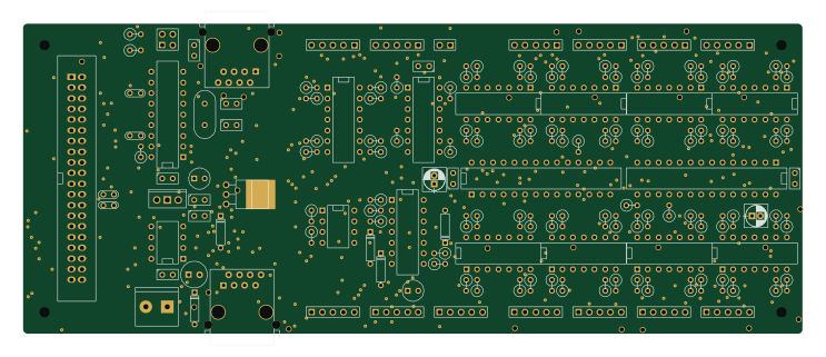
FullInterlockingPlantCANPower
185.4 × 73.7 mm151 parts2LCC-BY-4.024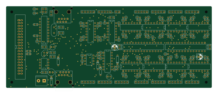
FullInterlockingPlantCAN
185.4 × 73.7 mm150 parts2LCC-BY-4.024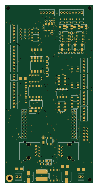
TivaMultiFunctionBoard
76.2 × 153.7 mm114 parts2LCC-BY-4.024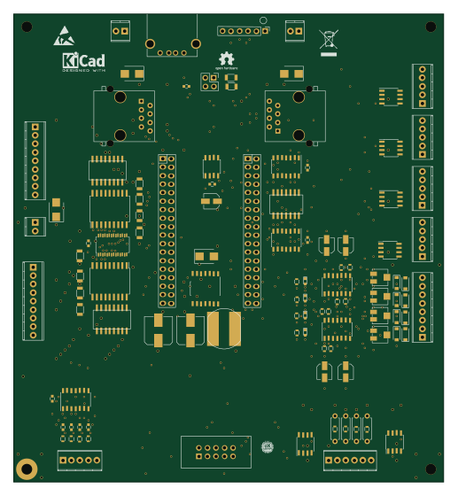
PocketBeagleMultifuntion
128.3 × 139.7 mm111 parts2LCC-BY-4.024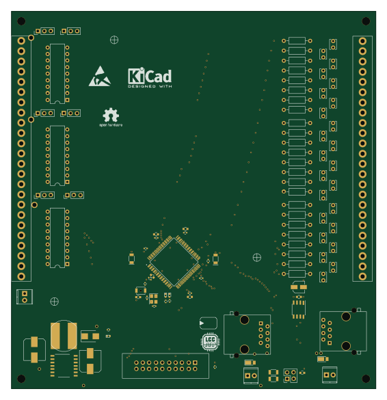 NXP
NXPLPC1768-MultiIOBoard
141 × 146.1 mm106 parts2LCC-BY-4.024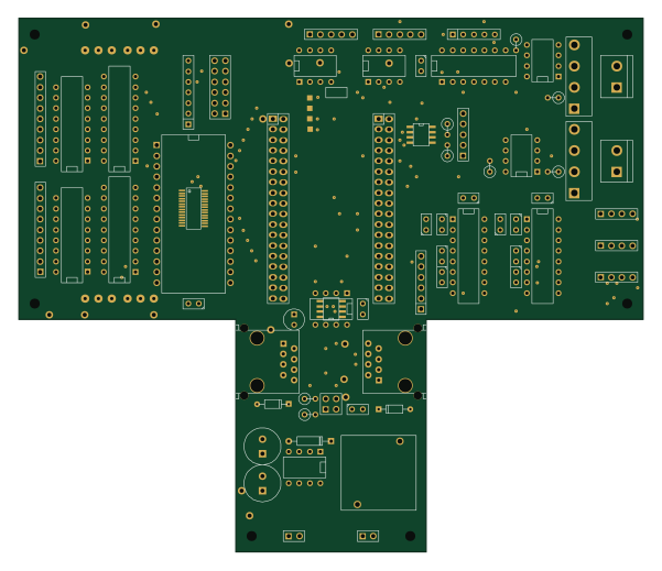
PocketBeaglePWMHalfSiding+ABSSlave
149.9 × 128.3 mm75 parts2LCC-BY-4.024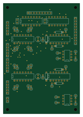
QuadSMC
69.9 × 101.6 mm56 parts2LCC-BY-4.024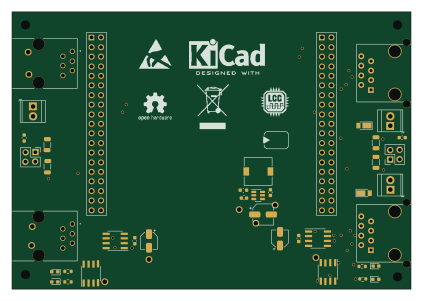
STM32F767ZI LCC PNET Router
105.6 × 73.3 mm41 parts2LCC-BY-4.024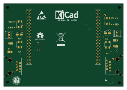
STM32F767ZI LCC Repeater
105.6 × 73.3 mm28 parts2LCC-BY-4.024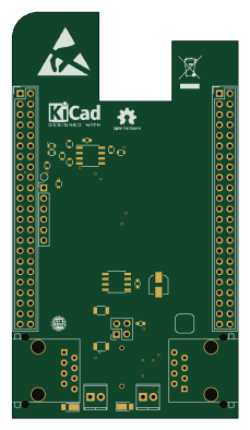
LCCCANCape
54.6 × 98.3 mm27 parts2LCC-BY-4.024
Similar boards
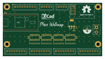 NXP
NXP32Bit shift register
MaltWhiskey
100 × 54 mm56 parts4LNo license763 NXP
NXPMega-Cube-Board
200 × 54 mm100 parts4LNo license763 NXP
NXPMCL64
MicroCoreLabs
39.3 × 61.8 mm9 parts4LNo license532 NXP
NXPROM Emulator
21.5 × 37.1 mm5 parts2LNo license532 NXP
NXPMCLZ8
37.1 × 61.5 mm6 parts4LNo license532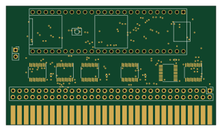 NXP
NXPXTMAX
81 × 46 mm14 parts4LNo license532