
Motor module

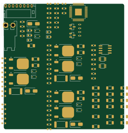
About the Motor module
Motor module is an open source PCB design by RoboJackets, published on GitHub under the Apache-2.0 license. It is a 2-layer board measuring 64.5 × 66.9 mm, with 122 components from 42 distinct parts.
Other key parts include the STSPIN32G0A2, SN74LVC3G17DCUR and SN75157DR. By type, the board carries 47 resistors, 25 capacitors, 18 test points, 17 diodes, 8 transistors and 4 ICs.
It belongs with the robotics & motion designs in this gallery.
From the project
The KiCAD Design Files for Georgia Tech RoboJackets RoboCup Small Size League's Electrical Systems
If you are a new member to the RoboCup electrical team and have never used git version control before, we highly recommend that you familiarize yourself with it by reading this guide.
However, older boards in the archives were designed using EAGLE or PCB (a program that is part of the gEDA project)
Unfortunately, EAGLE and PCB are no longer supported by their respective companies, and are not available for download. If you need access to these files, you are on your own.
Main components on the Motor module
Motor module bill of materials (BOM)
122 components, 42 distinct parts — part numbers from the project's BOM.
| Qty | Part | Footprint | Refs |
|---|---|---|---|
| 1 | STSPIN32G0A2 | LQFP-48-1EP_7x7mm_P0.5mm_EP3.6x3.6mm | U1 |
| 2 | SN74LVC3G17DCUR | VSSOP-8_2.3x2mm_P0.5mm | U2, U4 |
| 1 | SN75157DR | SOIC-8_3.9x4.9mm_P1.27mm | U3 |
| 2 | BSS84AKW,115 | SOT-23 | Q1, Q2 |
| 6 | STD140N6F7 | TO-252-2 | Q3, Q4, Q5, Q6, Q7, Q8 |
| 1 | Motor Power In | JST_VH_S2P-VH_1x02_P3.96mm_Horizontal | J1 |
| 1 | Logical Conn. | JST_PH_S8B-PH-K_1x08_P2.00mm_Horizontal | J2 |
| 1 | 12 A 50 V | Fuse_1206_3216Metric | F1 |
| 1 | RESET | R_1206_3216Metric | TP1 |
| 1 | 5V | R_1206_3216Metric | TP2 |
| 1 | 3.3V | R_1206_3216Metric | TP3 |
| 1 | ENC_A | R_1206_3216Metric | TP4 |
| 1 | ENC_B | R_1206_3216Metric | TP5 |
| 3 | HS_x | R_1206_3216Metric | TP6, TP10, TP14 |
| 3 | LS_x | R_1206_3216Metric | TP7, TP11, TP15 |
| 3 | PHASE_x | R_1206_3216Metric | TP8, TP12, TP16 |
| 3 | ISENSE_x | R_1206_3216Metric | TP9, TP13, TP17 |
| 1 | OCCOMP | R_1206_3216Metric | TP18 |
| 1 | FAULT | LED_0603_1608Metric | D1 |
| 1 | DEBUG | LED_0603_1608Metric | D2 |
Show 22 more
| Qty | Part | Footprint | Refs |
|---|---|---|---|
| 4 | SMAJ24CA | D_SMA | D4, D13, D16, D19 |
| 2 | CUZ5V6,H3F | D_SOD-323F | D5, D6 |
| 1 | VDC OK | LED_0603_1608Metric | D7 |
| 1 | 5V OK | LED_0603_1608Metric | D8 |
| 1 | 3.3V OK | LED_0603_1608Metric | D9 |
| 6 | 1N4148WS | D_SOD-323 | D11, D12, D14, D15, D17, D18 |
| 5 | 100n | C_0603_1608Metric | C1, C4, C12, C13, C15 |
| 6 | 10u | C_0603_1608Metric | C2, C5, C6, C7, C8, C9 |
| 2 | 1u | C_0603_1608Metric | C3, C14 |
| 2 | 0.1n | C_0603_1608Metric | C10, C11 |
| 6 | 10u | C_1206_3216Metric | C16, C17, C19, C20, C22, C23 |
| 4 | 1n | C_0603_1608Metric | C18, C21, C24, C25 |
| 4 | 10k | R_0603_1608Metric | R1, R6, R7, R8 |
| 4 | 100 | R_0402_1005Metric | R2, R3, R4, R5 |
| 6 | 1k | R_0603_1608Metric | R9, R10, R11, R12, R13, R14 |
| 11 | 100 | R_0603_1608Metric | R15, R16, R17, R18, R25, R26, R27, R34 +3 |
| 3 | 5m±1% 3W | R_2512_6332Metric | R19, R28, R37 |
| 6 | 110±0.1% | R_0603_1608Metric | R20, R23, R29, R32, R38, R41 |
| 6 | 6.04k±0.1% | R_0603_1608Metric | R21, R22, R30, R31, R39, R40 |
| 3 | 3.01k±0.1% | R_0603_1608Metric | R24, R33, R42 |
| 3 | 3.3k | R_0603_1608Metric | R44, R45, R46 |
| 1 | 15k | R_0603_1608Metric | R47 |
Motor module design files
The KiCad project lives in the RoboJackets/robocup-pcb repository on GitHub; these links point at the commit this page was built from.
Motor module: common questions
How big is the Motor module?
The Motor module measures 64.5 × 66.9 mm, has 2 copper layers and is 1.6 mm thick.
How many components are on the Motor module?
122 components, from 42 distinct parts, with part numbers taken from the project's own BOM. The full bill of materials is listed on this page.
Where can I download the Motor module design files?
From the RoboJackets/robocup-pcb repository on GitHub, which has the KiCad layout, the schematic and the BOM; the links under Design files point to each one.
Can I use the Motor module design in my own project?
Yes, under the terms of its Apache-2.0 license, which RoboJackets chose for the repository.
More boards in robocup-pcb
Motorboard
132 × 96 mm286 parts4LApache-2.032 RP2040/RP2350
Kicker Board
141 × 146.5 mm123 parts4LApache-2.032 STM32
STM32Control v4.1-stm32
72.7 × 57.9 mm83 parts4LApache-2.032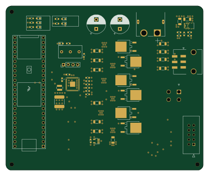 NXP
NXPMotortester v2.0
105.9 × 88.1 mm76 parts4LApache-2.032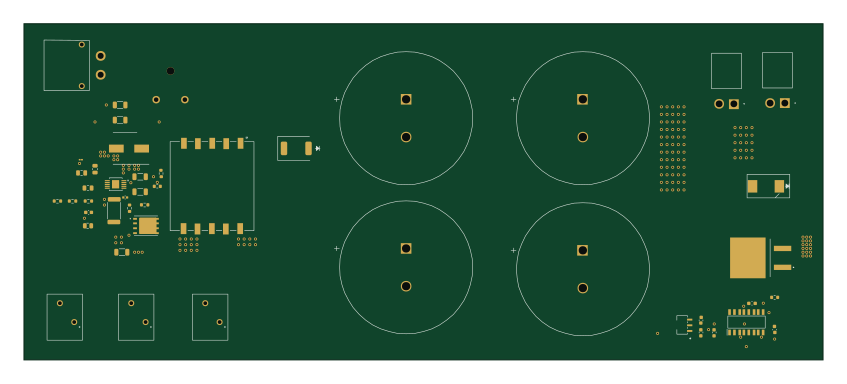
Flyback breakout v1.0
211.5 × 89 mm51 parts2LApache-2.032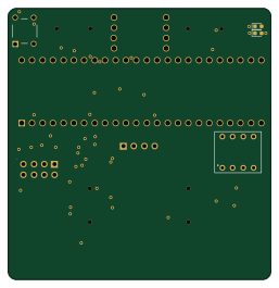 NXP
NXPControl v4.0
64 × 66 mm17 parts4LApache-2.032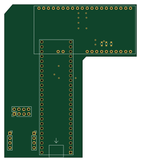 NXP
NXPTeensy adapter v3.0
69.3 × 80.7 mm8 parts4LApache-2.032
Similar boards

Stack chan
stack-chan
50 × 50 mm33 parts2LApache-2.01.7k
Cube batteryboard
willem-pennings
95 × 95 mm4 parts2LGPL-3.01.1k
Mesabob
rene-dev
87.5 × 50 mm44 parts2LGPL-3.0979
Bob
100 × 100 mm140 parts2LGPL-3.0979
Triple adapter
57 × 75 mm26 parts2LGPL-3.0979
Trollerv2
100 × 75 mm33 parts4LGPL-3.0979