
TicTacToe---Using-Digital-Logic

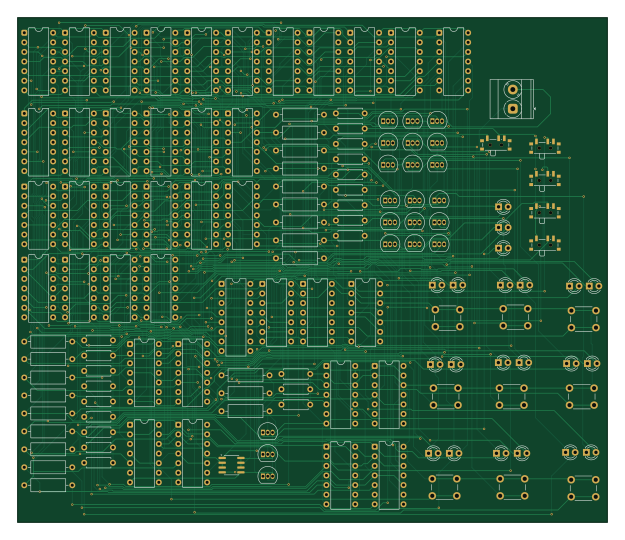
About the TicTacToe---Using-Digital-Logic PCB
TicTacToe---Using-Digital-Logic is an open source PCB design by rougeDAG, published on GitHub. It is a 2-layer board measuring 156 × 133.5 mm, with 139 components from 17 distinct parts.
Other key parts include the 74LS02, 74LS11, 74LS08, 74LS14 and 74LS74. By type, the board carries 42 resistors, 40 ICs, 21 transistors, 12 LEDs, 9 crystals and 1 battery holder.
From the project
A Tic Tac Toe game made completely using digital logic. A semester project for the course Digital System Design
A first year graded project I submitted for my course in Digital System Design (Winter Semester, Vellore Institue of Technology, Chennai). This is a Tic Tac Toe game that uses only digital logic to play the game. PCB Design was done on KiCad , an open source PCB Design software. I simulated the circuit in another open source digital simulator called Digital.exe (which is based on another software called Logisim) by Helmut Neemann which I downloaded from his GitHub repository. Digital.exe helped me immensely in my project as I cannot have simulated my project without this software for free.…
Main components on the TicTacToe---Using-Digital-Logic
TicTacToe---Using-Digital-Logic bill of materials (BOM)
139 components, 17 distinct parts.
| Qty | Part | Footprint | Refs |
|---|---|---|---|
| 3 | 74LS02 | DIP-14_W7.62mm | U1, U6, U8 |
| 12 | 74LS11 | DIP-14_W7.62mm | U2, U9, U10, U12, U13, U14, U24, U25 +4 |
| 5 | 74LS08 | DIP-14_W7.62mm | U3, U5, U7, U35, U36 |
| 2 | 74LS14 | DIP-14_W7.62mm | U4, U11 |
| 9 | 74LS74 | DIP-14_W7.62mm | U15, U16, U17, U18, U19, U20, U21, U22 +1 |
| 6 | 74LS32 | DIP-14_W7.62mm | U30, U31, U32, U33, U37, U38 |
| 1 | 74LS76 | DIP-16_W7.62mm | U34 |
| 1 | 74LS27 | DIP-14_W7.62mm | U39 |
| 1 | XL1509-5.0 | SOIC-8_3.9x4.9mm_P1.27mm | U40 |
| 21 | NPN | TO-92_Inline | Q1, Q2, Q3, Q4, Q5, Q6, Q7, Q8 +13 |
| 9 | LED | LED_D3.0mm | x1, x2, x3, x4, x5, x6, x7, x8 +1 |
| 1 | 12V | TerminalBlock_Phoenix_MKDS-3-2-5.08_1x02_P5.08mm_Horizontal | BT1 |
| 5 | SW_Push | SW_SPDT_PCM12 | D_Clear1, D_Preset1, T_Clear1, T_Preset1, buckEn1 |
| 9 | SW_Push | SW_PUSH_6mm | button1, button2, button3, button4, button5, button6, button7, button8 +1 |
| 12 | LED | LED_D3.0mm | DRAW1, O_WON1, X_WON1, o1, o2, o3, o4, o5 +4 |
| 21 | 6800 | R_Axial_DIN0309_L9.0mm_D3.2mm_P12.70mm_Horizontal | R1, R3, R5, R7, R9, R11, R13, R15 +13 |
| 21 | 150 | R_Axial_DIN0207_L6.3mm_D2.5mm_P7.62mm_Horizontal | R2, R4, R6, R8, R10, R12, R14, R16 +13 |
TicTacToe---Using-Digital-Logic design files
The KiCad project lives in the rougeDAG/TicTacToe---Using-Digital-Logic repository on GitHub; these links point at the commit this page was built from.
TicTacToe---Using-Digital-Logic: common questions
How big is the TicTacToe---Using-Digital-Logic PCB?
The TicTacToe---Using-Digital-Logic measures 156 × 133.5 mm, has 2 copper layers and is 1.6 mm thick.
How many components are on the TicTacToe---Using-Digital-Logic?
139 components, from 17 distinct parts. The full bill of materials is listed on this page.
Where can I download the TicTacToe---Using-Digital-Logic design files?
From the rougeDAG/TicTacToe---Using-Digital-Logic repository on GitHub, which has the KiCad layout and the schematic; the links under Design files point to each one.
Can I use the TicTacToe---Using-Digital-Logic design in my own project?
The repository has no license, so all rights stay with rougeDAG. Use it as a reference, and ask the author before reusing the design.