
Capacitive soil sensor

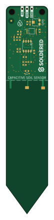
About the Capacitive soil sensor PCB
Capacitive soil sensor is an open source PCB design by SolderedElectronics, published on GitHub under the TAPR-OHL-1.0 license. It is a 2-layer board measuring 22 × 109 mm, with 25 components from 17 distinct parts.
Other key parts include the TLC555CD and SGM358YMS/TR. By type, the board carries 11 resistors, 6 capacitors, 2 ICs, 1 relay and 1 diode.
It belongs with the sensors designs in this gallery.
From the project
Hardware design, BOM, gerbers and 3D files for Capacitive-soil-sensor designed by Soldered Electronics.
How many times have you watered your plants and feared you overdid it? With the capacitive soil sensor, those worries are a thing of the past!
Most cheap soil sensors work on the resistance principle, where there are two prongs and the sensor measures the conductivity between them. They work fine at first, but eventually begin to oxidize due to the exposed metal. Even if they are gold plated! Due to oxidation, the resistance goes up and up, so you have to constantly recalibrate your code. Also, resistance measurements do not always work in loose soil.

Main components on the Capacitive soil sensor
Capacitive soil sensor bill of materials (BOM)
25 components, 17 distinct parts — part numbers from the project's BOM.
| Qty | Part | Footprint | Refs |
|---|---|---|---|
| 1 | TLC555CD | SOIC−8 | U1 |
| 1 | SGM358YMS/TR | MSOP-8 | U2 |
| 2 | HOLE_3.2mm | HOLE_3.2mm | H1, H2 |
| 1 | HEADER_MALE_3X1 | HEADER_MALE_3X1 | K1 |
| 2 | PAD_2x1.5 | PAD_2x1.5 | PAD1, PAD2 |
| 1 | BAT20J | SOD-323 | D1 |
| 1 | 1u | 0603C | C1 |
| 1 | 10n | 0603C | C2 |
| 3 | 100n | 0603C | C3, C7, C8 |
| 1 | 470p | 0603C | C4 |
| 1 | 1M | 0603R | R1 |
| 3 | 10k | 0603R | R2, R5, R9 |
| 1 | 330R | 0603R | R3 |
| 1 | 1K6 | 0603R | R4 |
| 2 | 47k | 0603R | R6, R11 |
| 2 | 100k | 0603R | R7, R10 |
| 1 | tc33x-2-103e | tc33x-2-103e | R8 |
Capacitive soil sensor design files
The KiCad project lives in the SolderedElectronics/Capacitive-soil-sensor-hardware-design repository on GitHub; these links point at the commit this page was built from.
Capacitive soil sensor: common questions
How big is the Capacitive soil sensor PCB?
The Capacitive soil sensor measures 22 × 109 mm, has 2 copper layers and is 1.6 mm thick.
How many components are on the Capacitive soil sensor?
25 components, from 17 distinct parts, with part numbers taken from the project's own BOM. The full bill of materials is listed on this page.
Where can I download the Capacitive soil sensor design files?
From the SolderedElectronics/Capacitive-soil-sensor-hardware-design repository on GitHub, which has the KiCad layout, the schematic and the BOM; the links under Design files point to each one.
Can I use the Capacitive soil sensor design in my own project?
Yes, under the terms of its TAPR-OHL-1.0 license, which SolderedElectronics chose for the repository.
More boards in Capacitive-soil-sensor-hardware-design

Similar boards

Sensor smd
scottbez1
40 × 20 mm5 parts2LApache-2.04.2k
Sensors
StuckAtPrototype
15.2 × 9 mm14 parts4LApache-2.03.8k
Microphone
Mentra-Community
5.5 × 6.1 mm6 parts2LMIT1.2k
TemperaturePCB PANEL
stuartpittaway
116 × 75.5 mm178 parts2LCC-BY-NC-4.01.1k
Pots
shanteacontrols
390 × 93 mm75 parts2LApache-2.0956
ButtonsLEDs
390 × 37 mm82 parts2LApache-2.0956