
Modulator V1p2

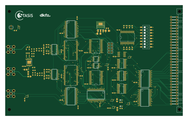
About the Modulator V1p2 PCB
Modulator V1p2 is an open source PCB design by sOrzada, published on GitHub under the CERN-OHL-W-2.0 license. It is a 6-layer board measuring 160 × 100 mm, with 112 components from 44 distinct parts.
Other key parts include the 74ALVC00, SN74LVC04ANS, 74HC688DW, 74LVC1G17DCK and SN74LVC16373. By type, the board carries 41 capacitors, 28 ICs, 26 resistors, 8 inductors, 3 crystals and 2 diodes.
From the project
This is the repository for the exposition hardware of the STASIS project.
This Folder contains the PCBs and Housings for the Control System of the STASIS project's RF exposition system. The PCBs are provided in two different formats: Eagle and KiCAD. The Housings-folder contains .step files for the housings and front panels of the Eurocards.
Main components on the Modulator V1p2
Modulator V1p2 bill of materials (BOM)
112 components, 44 distinct parts.
| Qty | Part | Footprint | Refs |
|---|---|---|---|
| 1 | 74ALVC00 | SO14_88 | IC1 |
| 1 | SN74LVC04ANS | SO14_88 | IC2 |
| 3 | 74HC688DW | SO20W_85 | IC3, IC4, IC16 |
| 4 | 74LVC1G17DCK | SC70-5_86 | IC5, IC13, IC14, IC18 |
| 1 | SN74LVC16373 | SSOP48DL_83 | IC6 |
| 1 | SN74LVC1G32IDCKREP | SC70-5_87 | IC7 |
| 2 | SN74CB3Q16245DLR | SSOP48DL_83 | IC8, IC9 |
| 2 | SN74LVCH16244ADLR | SSOP48DL_83 | IC10, IC20 |
| 1 | 74LVC1G04DCK | SC70-5_87 | IC11 |
| 1 | 74LVC1G08DCK | SC70-5_87 | IC15 |
| 1 | SN74LVC02AD | SO14_88 | IC24 |
| 2 | SRAM_64K_16BIT | TSOPII-Z44 | U$1, U$2 |
| 2 | AD9754 | TSSOP28 | U$3, U$4 |
| 1 | DS1100LZ-20LZ | SO-08 | U$5 |
| 1 | AD8345E | TSSOP16EXP | U$6 |
| 2 | 74LV393PW | TSSOP14 | U$7, U$8 |
| 1 | AZ1117IH-3.3TRG1 | SOT223 | U$9 |
| 1 | ETC1-1-13 | ETC1-1-13 | U$12 |
| 3 | SMA_CON-H | BU-SMA-H | X1, X2, X3 |
| 1 | BUS | VG64B_79 | J1 |
Show 24 more
| Qty | Part | Footprint | Refs |
|---|---|---|---|
| 1 | PINHD-2X4 | 2X04_16378166 | JP1 |
| 1 | SWS008 | SMS-008_362 | S1 |
| 1 | 10mA 2.2-2.4V | LED3MM_259 | LED1 |
| 2 | BAT60J | SOD323_ST_210 | D1, D2 |
| 4 | 1uH | L2012C_334 | L1, L2, L5, L6 |
| 4 | 1.5uH | L2012C_334 | L3, L4, L7, L8 |
| 8 | 100nF | C0603_334 | C1, C2, C3, C4, C11, C12, C19, C20 |
| 2 | 110pF | C0603_334 | C5, C8 |
| 2 | 270pF | C0603_334 | C6, C9 |
| 2 | 220pF | C0603_334 | C7, C10 |
| 1 | 10µF | C1206_334 | C13 |
| 1 | 22µF | C1206_334 | C14 |
| 3 | 10nF | C0402_334 | C15, C16, C33 |
| 2 | 1nF | C0805_334 | C17, C18 |
| 20 | 10nF | C0603_334 | C21, C22, C23, C24, C25, C26, C27, C28 +12 |
| 11 | 100k | R0603_334 | R1, R2, R3, R19, R20, R21, R22, R23 +3 |
| 2 | 2k | R0603_334 | R4, R5 |
| 4 | 140 | R0603_334 | R6, R7, R8, R9 |
| 2 | 220 | R0603_334 | R10, R11 |
| 2 | NP | R0805_334 | R12, R14 |
| 1 | 0 | R0805_334 | R13 |
| 2 | 1k | R0603_334 | R15, R16 |
| 1 | 120 | R0603_334 | R17 |
| 1 | 50 | R0603_334 | R18 |
Modulator V1p2 design files
The KiCad project lives in the sOrzada/STASIS_Exposure_Hardware repository on GitHub; these links point at the commit this page was built from.
Modulator V1p2: common questions
How big is the Modulator V1p2 PCB?
The Modulator V1p2 measures 160 × 100 mm, has 6 copper layers and is 1.6 mm thick.
How many components are on the Modulator V1p2?
112 components, from 44 distinct parts. The full bill of materials is listed on this page.
Where can I download the Modulator V1p2 design files?
From the sOrzada/STASIS_Exposure_Hardware repository on GitHub, which has the KiCad layout and the schematic; the links under Design files point to each one.
Can I use the Modulator V1p2 design in my own project?
Yes, under the terms of its CERN-OHL-W-2.0 license, which sOrzada chose for the repository.
More boards in STASIS_Exposure_Hardware
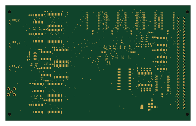
Timing Control V1p1
160 × 100 mm101 parts6LCERN-OHL-W-2.00
Stripline
450 × 100 mm81 parts2LCERN-OHL-W-2.00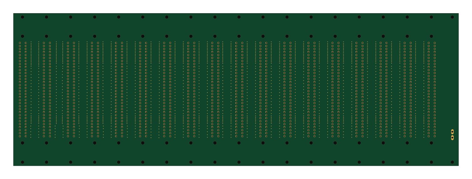
Backplane
376 × 128.6 mm75 parts2LCERN-OHL-W-2.00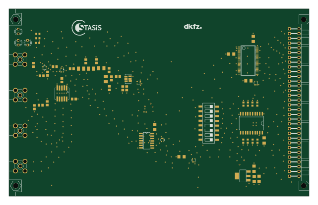
Signal source V1p0
160 × 100 mm63 parts2LCERN-OHL-W-2.00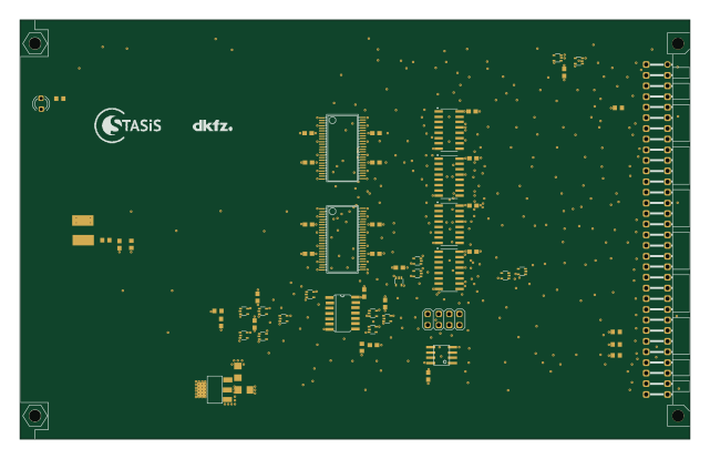
SPI2Parallel v1p1
160 × 100 mm63 parts4LCERN-OHL-W-2.00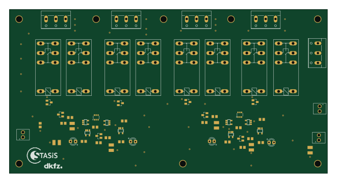
Power Distribution V1.1
165 × 85 mm61 parts2LCERN-OHL-W-2.00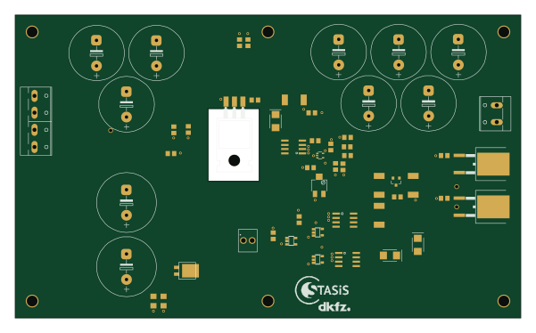
VoltageControl V1p1
150 × 90 mm55 parts2LCERN-OHL-W-2.00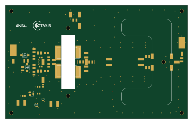
HPA Module V1p1
160 × 100 mm52 parts2LCERN-OHL-W-2.00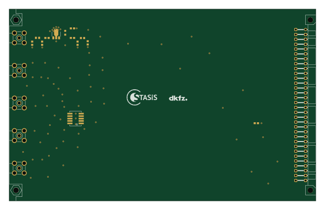
RF Splitter active
160 × 100 mm19 parts2LCERN-OHL-W-2.00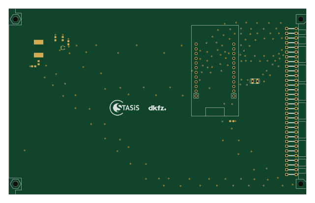
USB2SPI
160 × 100 mm12 parts2LCERN-OHL-W-2.00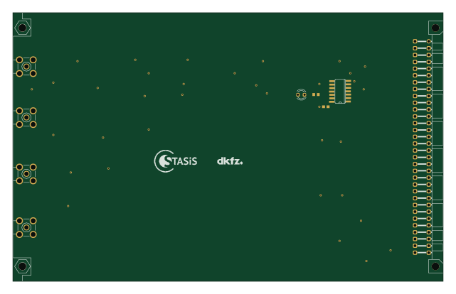
TR UBL Splitter V1p1
160 × 100 mm9 parts2LCERN-OHL-W-2.00