
Telemetry Onboard

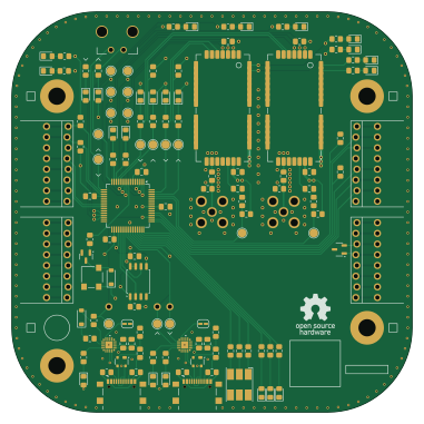
About the Telemetry Onboard PCB
Telemetry Onboard is an open source PCB design by Spaceflight-Rocketry-Giessen-e-V, published on GitHub under the CERN-OHL-S-2.0 license. It is a 4-layer board measuring 95 × 95 mm, with 138 components from 43 distinct parts.
Other key parts include the CP2102N, AVR128DB64X-XPT, RC1780HP-RC232, RC1701HP-RC232 and W25Q80DVSSIG. By type, the board carries 50 resistors, 29 diodes, 17 test points, 13 capacitors, 6 ICs and 5 connectors.
It belongs with the rf & radio designs in this gallery.
From the project
Open-Source Rocket Telemetry System Based On Radiocrafts RC232 Radio Modules
- Electronics Hardware - KiCad Design Files - PDF Schematic - Interactive Schematic / iBOM - BOM - Gerber Files - PCB 3D Model - PCB Images - Mounting Structure - Firmware - 869 MHz QFH Antenna (not yet available)
Main components on the Telemetry Onboard
Telemetry Onboard bill of materials (BOM)
138 components, 43 distinct parts — part numbers from the project's BOM.
| Qty | Part | Footprint | Refs |
|---|---|---|---|
| 2 | CP2102N | QFN20_CP2102N_SIL | U1, U2 |
| 1 | AVR128DB64X-XPT AVR128DB64x-xPT | TQFP-64_10x10mm_P0.5mm | U3 |
| 1 | RC1780HP-RC232 | Radiocrafts RC1780HP-RC232 | U4 |
| 1 | RC1701HP-RC232 | Radiocrafts RC1780HP-RC232 | U5 |
| 1 | W25Q80DVSSIG | SOIC-8_5.3x5.3mm_P1.27mm | U6 |
| 4 | M4 Mounting Hole | M4 Mounting Hole | M1, M2, M3, M4 |
| 1 | MMBT4401-TP | SOT-23 | Q1 |
| 2 | USB-C | GCT_USB4216-03-A_REVA | J1, J2 |
| 2 | RFPC-SMA28-F | RFPC-SMA28-F | J3, J4 |
| 1 | MOLEX_MICROFIT_2PIN Molex_MicroFit_2pin | Molex_MicroFit_2pin | J5 |
| 1 | Stackable Socket 1x8 | JL1 | JL1 |
| 1 | Stackable Socket 1x8 | JL2 | JL2 |
| 1 | Stackable Socket 1x8 | JL3 | JL3 |
| 1 | Stackable Socket 1x8 | JL4 | JL4 |
| 1 | Stackable Socket 1x8 | JR1 | JR1 |
| 1 | Stackable Socket 1x8 | JR2 | JR2 |
| 1 | Stackable Socket 1x8 | JR3 | JR3 |
| 1 | Stackable Socket 1x8 | JR4 | JR4 |
| 1 | CMT-0525-75-SMT CMT-0525-75-SMT-TR | Buzzer XDCR_CMT-0525-75-SMT-TR | LS1 |
| 17 | TestPoint | Test Point | TP1, TP2, TP3, TP4, TP5, TP6, TP7, TP8 +9 |
Show 23 more
| Qty | Part | Footprint | Refs |
|---|---|---|---|
| 4 | ~ | R_0805_2012Metric_Pad1.20x1.40mm_HandSolder | ZP1, ZP2, ZS1, ZS2 |
| 9 | orange | LED_0805_2012Metric_Pad1.15x1.40mm_HandSolder | D1, D2, D3, D7, D15, D16, D17, D18 +1 |
| 1 | Cree RGB LED | Cree RGB LED | D4 |
| 2 | SP0503BAHTG | SOT-143 | D5, D8 |
| 5 | green | LED_0805_2012Metric_Pad1.15x1.40mm_HandSolder | D6, D11, D12, D25, D27 |
| 7 | red | LED_0805_2012Metric_Pad1.15x1.40mm_HandSolder | D9, D20, D21, D22, D23, D28, D29 |
| 1 | BAT43 | D_SOD-123 | D10 |
| 1 | WE-TVS_SOT23-3L_824021 | SOT-23-3 | D13 |
| 1 | MMSD4148T1G | D_SOD-123 | D14 |
| 2 | yellow | LED_0805_2012Metric_Pad1.15x1.40mm_HandSolder | D24, D26 |
| 2 | 4U7 4u7 | C_0805_2012Metric_Pad1.18x1.45mm_HandSolder | C1, C3 |
| 2 | 0U1 0u1 | C_0805_2012Metric_Pad1.18x1.45mm_HandSolder | C2, C4 |
| 7 | 1u | C_0805_2012Metric_Pad1.18x1.45mm_HandSolder | C5, C6, C7, C8, C10, C12, C13 |
| 2 | 1n | C_0805_2012Metric_Pad1.18x1.45mm_HandSolder | C9, C11 |
| 20 | 560R | R_0805_2012Metric_Pad1.20x1.40mm_HandSolder | R1, R2, R3, R4, R5, R6, R11, R12 +12 |
| 4 | 5K1 5k1 | R_0805_2012Metric_Pad1.20x1.40mm_HandSolder | R7, R8, R13, R14 |
| 2 | 47K 47k | R_0805_2012Metric_Pad1.20x1.40mm_HandSolder | R9, R15 |
| 2 | 22K 22k | R_0805_2012Metric_Pad1.20x1.40mm_HandSolder | R10, R16 |
| 2 | 470R | R_0805_2012Metric_Pad1.20x1.40mm_HandSolder | R18, R19 |
| 1 | 180R | R_0805_2012Metric_Pad1.20x1.40mm_HandSolder | R22 |
| 11 | 5K6 5k6 | R_0805_2012Metric_Pad1.20x1.40mm_HandSolder | R23, R24, R25, R26, R27, R28, R29, R30 +3 |
| 2 | 2K7 2k7 | R_0805_2012Metric_Pad1.20x1.40mm_HandSolder | R32, R34 |
| 6 | 1k | R_0805_2012Metric_Pad1.20x1.40mm_HandSolder | R41, R42, R43, R44, R49, R50 |
Telemetry Onboard design files
The KiCad project lives in the Spaceflight-Rocketry-Giessen-e-V/Telemetry repository on GitHub; these links point at the commit this page was built from.
Telemetry Onboard: common questions
How big is the Telemetry Onboard PCB?
The Telemetry Onboard measures 95 × 95 mm, has 4 copper layers and is 1.6 mm thick.
How many components are on the Telemetry Onboard?
138 components, from 43 distinct parts, with part numbers taken from the project's own BOM. The full bill of materials is listed on this page.
Where can I download the Telemetry Onboard design files?
From the Spaceflight-Rocketry-Giessen-e-V/Telemetry repository on GitHub, which has the KiCad layout, the schematic and the BOM; the links under Design files point to each one.
Can I use the Telemetry Onboard design in my own project?
Yes, under the terms of its CERN-OHL-S-2.0 license, which Spaceflight-Rocketry-Giessen-e-V chose for the repository.
More boards in Telemetry
Similar boards
Hat
pa3gsb
65 × 56 mm81 parts2LNo license675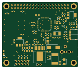
Radioberry juice
65 × 56 mm87 parts2LNo license675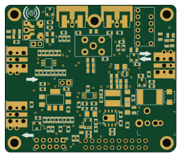
Radioberry preamp
65 × 56 mm137 parts2LNo license675
Goodwatch20
travisgoodspeed
25.6 × 27.6 mm20 parts2LNo license568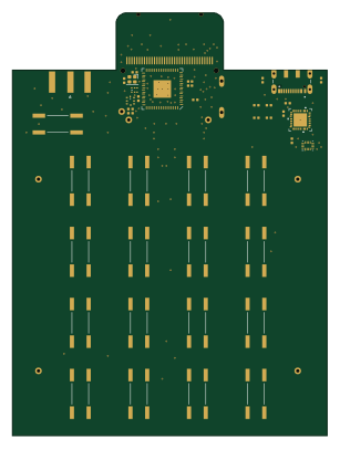
GoodPocketWatch
75.2 × 101.2 mm56 parts2LNo license568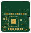
Goodwatch31
25.6 × 27.6 mm23 parts2LNo license568