
18650-Tester

About the 18650-Tester PCB
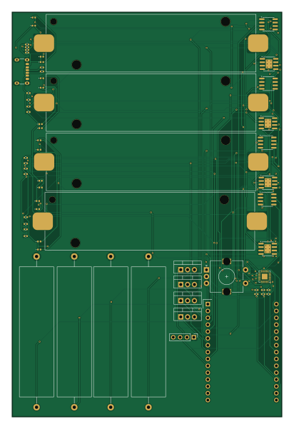
18650-Tester is an open source ESP32 PCB design by Studented0, published on GitHub under the MIT license. It is a 2-layer board measuring 100 × 150 mm, with 65 components from 19 distinct parts.
Its main chip is the ESP32-DevKitC-30PIN, from the ESP32 family. Other key parts include the TCA9548AMRGER, INA219AIDR and TP4056-42-ESOP8. By type, the board carries 16 LEDs, 10 ICs, 6 resistors, 4 transistors, 4 battery holders and 2 connectors.
It belongs with the power & battery, iot & wireless and displays & leds designs in this gallery.
From the project
Tests 18650 cells for voltage, internal resistance, capacity, and more.
A 4-channel 18650 battery analyzer. Tests up to 4 cells at once and measures voltage, capacity in mAh, and internal resistance per channel. Results show on a small OLED with a rotary encoder to navigate, and a WiFi dashboard to start and stop tests remotely/edit settings.
My science fair project was a 3S34P battery pack from 34 salvaged 18650 cells. I bought a cheap tester off Amazon to sort them but I wanted to know how it actually worked. I also wanted an excuse to learn PCB design. CellScan is the result, a two-layer PCB with SMD assembly through JLCPCB.
Main components on the 18650-Tester
18650-Tester bill of materials (BOM)
65 components, 19 distinct parts — part numbers from the project's BOM.
| Qty | Part | Footprint | Refs |
|---|---|---|---|
| 1 | ESP32-DevKitC-30PIN | ESP32-DevKitC-30PIN | U1 |
| 1 | TCA9548AMRGER | Texas_RGE0024C_VQFN-24-1EP_4x4mm_P0.5mm_EP2.1x2.1mm | U2 |
| 4 | INA219AIDR INA219AxD | SOIC-8_3.9x4.9mm_P1.27mm | U3, U4, U5, U6 |
| 4 | TP4056-42-ESOP8 | SOIC-8-1EP_3.9x4.9mm_P1.27mm_EP2.41x3.3mm_ThermalVias | U7, U8, U9, U10 |
| 4 | IRLZ44N | TO-220-3_Vertical | Q1, Q2, Q3, Q4 |
| 1 | OLED DISPLAY | PinHeader_1x04_P2.54mm_Vertical | J1 |
| 1 | USB_C_Receptacle_PowerOnly_6P | USB_C_Receptacle_GCT_USB4125-xx-x-0190_6P_TopMnt_Horizontal | J3 |
| 4 | 10k | R_0402_1005Metric | BAT1.1, BAT2.1, BAT3.1, BAT4.1 |
| 4 | 1.2k | R_0402_1005Metric | BAT1.2, BAT2.2, BAT3.2, BAT4.2 |
| 8 | 100nF | C_0402_1005Metric | BAT1.3, BAT1.4, BAT2.3, BAT2.4, BAT3.3, BAT3.4, BAT4.3, BAT4.4 |
| 4 | Battery_Cell | BatteryHolder_Keystone_1042_1x18650 | BT1, BT2, BT3, BT4 |
| 3 | 100NF C | C_0402_1005Metric | ENCC1, ENCC2, ENCC3 |
| 3 | 10K 10k | R_0402_1005Metric | ENCR1, ENCR2, ENCR3 |
| 1 | RotaryEncoder_Switch_MP | RotaryEncoder_Alps_EC11E-Switch_Vertical_H20mm | SW1 |
| 8 | 1k | LED_0402_1005Metric | BAT1GREEN1, BAT1RED1, BAT2GREEN1, BAT2RED1, BAT3GREEN1, BAT3RED1, BAT4GREEN1, BAT4RED1 |
| 4 | GREEN | LED_0402_1005Metric | GREEN1, GREEN2, GREEN3, GREEN4 |
| 4 | RED | LED_0402_1005Metric | RED1, RED2, RED3, RED4 |
| 4 | 2ohm 10watt | R_Axial_Power_L48.0mm_W12.5mm_P55.88mm | R1, R2, R3, R4 |
| 2 | 5.1K 5.5k | R_0402_1005Metric | R5, R6 |
18650-Tester design files
The KiCad project lives in the Studented0/18650-Tester repository on GitHub; these links point at the commit this page was built from.
18650-Tester: common questions
What microcontroller does the 18650-Tester use?
The 18650-Tester is built around the ESP32-DevKitC-30PIN, from the ESP32 family.
How big is the 18650-Tester PCB?
The 18650-Tester measures 100 × 150 mm, has 2 copper layers and is 1.6 mm thick.
How many components are on the 18650-Tester?
65 components, from 19 distinct parts, with part numbers taken from the project's own BOM. The full bill of materials is listed on this page.
Where can I download the 18650-Tester design files?
From the Studented0/18650-Tester repository on GitHub, which has the KiCad layout, the schematic and the BOM; the links under Design files point to each one.
Can I use the 18650-Tester design in my own project?
Yes, under the terms of its MIT license, which Studented0 chose for the repository.
Can I test firmware for the 18650-Tester without the hardware?
Yes. HardLabs builds a simulation of the board from its netlist and BOM, so you can run and debug ESP32 firmware against it before you order a PCB.
Similar boards
 ESP32
ESP32Open Book Abridged Edition
joeycastillo
85 × 115 mm65 parts2LCC-BY-SA-4.08.1k ESP32
ESP32Esp32 minimal
atopile
36.2 × 26.8 mm20 parts2LMIT4.0k ESP32
ESP32Badge
56.3 × 39 mm239 parts4LMIT4.0k ESP32
ESP32Controller
StuckAtPrototype
29 × 74 mm58 parts4LApache-2.03.8k ESP32
ESP32Racer
36 × 50.2 mm70 parts4LApache-2.03.8k ESP32
ESP32Bitaxe
skot
56.5 × 99.8 mm86 parts4LCERN-OHL-S-2.01.4k