
EEG-I-LAB

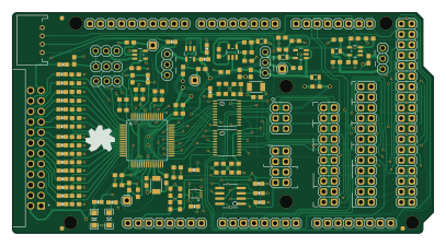
About the EEG-I-LAB PCB
EEG-I-LAB is an open source PCB design by Tahacrpc, published on GitHub under the CERN-OHL-1.2 license. It is a 4-layer board measuring 101.6 × 53.3 mm, with 139 components from 47 distinct parts.
Other key parts include the ADS1299IPAG, TPS72325DBVT, TPS73225DBVT, 24LC256-I/SN and TPS60403DBVT. By type, the board carries 71 capacitors, 29 resistors, 18 jumpers, 11 ICs, 4 test points and 4 inductors.
It belongs with the dev boards & breakouts designs in this gallery.
From the project
ADS1299 Tabanlı 8 Kanallı EEG Tasarımı
The Altium PcbDoc and PcbLibs are privacy-sanitized publication copies: a same-length redaction of a local account name, with no design change. hackeeg-shield.IntLib is withheld. See altium-release/PUBLICATIONSANITIZATION.md`. The upstream STEP models are not included because their vendor licence terms are not stated.
The work-in-progress Altium working copy, its intermediate checkpoints 01–06, and the post-release CAMtastic re-save are not included on purpose. The release PcbDoc is checkpoint 07RELEASE (SHA-256 60f874cf…e5c5f1`).
Main components on the EEG-I-LAB
EEG-I-LAB bill of materials (BOM)
139 components, 47 distinct parts.
| Qty | Part | Footprint | Refs |
|---|---|---|---|
| 1 | ADS1299IPAG | TQFP64 | IC1 |
| 1 | TPS72325DBVT | SOT23-5 | IC2 |
| 1 | TPS73225DBVT | SOT23-5 | IC3 |
| 1 | 24LC256-I/SN 24AA256UID | SO-08 | IC5 |
| 1 | TPS60403DBVT | SOT23-5 | IC6 |
| 2 | OPA376DBV | SOT23-5 | IC7, IC8 |
| 1 | — | VFSOP-8 | IC9 |
| 2 | TXB0108PWR | TSSOP20 | IC10, IC11 |
| 1 | — | ENDLESSKNOT-MEDIUM | U$7 |
| 1 | CONFIG1 | 2X12 | JP1 |
| 1 | CONFIG0 | 2X10 | JP2 |
| 1 | BOARD_ADDRESS | 2X04 | JP3 |
| 1 | 5V-2.5V | 1X03 | JP4 |
| 1 | -2.5V-GND | 1X03 | JP5 |
| 1 | SRB1-BIAS | 1X03 | JP6 |
| 1 | SRB2-REF_ELEC | 1X03 | JP7 |
| 1 | SRB1-REF_ELEC | 1X03 | JP8 |
| 1 | BIASOUT_BIASIN_BIAS_ELEC | 1X03 | JP9 |
| 1 | External Sync | JST-4-PTH | JP15 |
| 1 | Electrodes | OST_302-R241 | JP16 |
Show 27 more
| Qty | Part | Footprint | Refs |
|---|---|---|---|
| 1 | PWMH | 1X10 | JP20 |
| 1 | PWML | 1X08 | JP21 |
| 1 | COMMUNICATION | 1X08 | JP22 |
| 1 | XIO | 2X18 | JP23 |
| 1 | ADCH | 1X08 | JP24 |
| 1 | ADCL | 1X08 | JP25 |
| 1 | POWER | 1X08 | JP26 |
| 1 | AVDD_TEST_POINT | 1X01 | TP1 |
| 1 | AVSS_TEST_POINT | 1X01 | TP2 |
| 1 | AGND_TEST_POINT | 1X01 | TP3 |
| 1 | VREFP_TEST_POINT | 1X01 | TP4 |
| 1 | RED | LED-1206 | D1 |
| 1 | BLUE | LED-1206 | D2 |
| 4 | 3.3 uH | 0805 | L1, L2, L3, L4 |
| 3 | 2.2uF | 0603-CAP | C1, C4, C28 |
| 3 | 10 uF | 0603-CAP | C2, C5, C16 |
| 6 | 10uF | 0603-CAP | C3, C6, C22, C24, C27, C64 |
| 24 | 1uF | 0603-CAP | C7, C9, C11, C13, C15, C18, C19, C21 +16 |
| 14 | 0.1uF | 0603-CAP | C8, C10, C12, C14, C20, C23, C33, C53 +6 |
| 2 | 100uF | 1210 | C17, C25 |
| 2 | 0.01uF | 0603-CAP | C31, C66 |
| 17 | 4.7nF | 0603-CAP | C34, C35, C36, C37, C38, C39, C40, C41 +9 |
| 2 | 270 | 0603-RES | R1, R18 |
| 6 | 10k | 0603-RES | R2, R3, R4, R19, R20, R21 |
| 1 | 3.98K | 0603-RES | R6 |
| 2 | 2M | 0603-RES | R22, R23 |
| 18 | 4.99k | 0603-RES | R24, R25, R34, R35, R36, R37, R38, R39 +10 |
EEG-I-LAB design files
The KiCad project lives in the Tahacrpc/EEG-I-LAB repository on GitHub; these links point at the commit this page was built from.
EEG-I-LAB: common questions
How big is the EEG-I-LAB PCB?
The EEG-I-LAB measures 101.6 × 53.3 mm, has 4 copper layers and is 1.6062 mm thick.
How many components are on the EEG-I-LAB?
139 components, from 47 distinct parts. The full bill of materials is listed on this page.
Where can I download the EEG-I-LAB design files?
From the Tahacrpc/EEG-I-LAB repository on GitHub, which has the KiCad layout and the schematic; the links under Design files point to each one.
Can I use the EEG-I-LAB design in my own project?
Yes, under the terms of its CERN-OHL-1.2 license, which Tahacrpc chose for the repository.
Similar boards
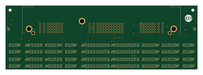
Breakout 112pin Connector
rusefi
174 × 58 mm39 parts2LGPL-3.01.2k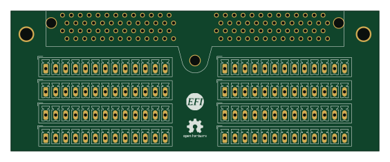
Eecv breakout
140.8 × 53.7 mm9 parts4LGPL-3.01.2k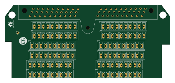
Breakout 60pin EEC-IV
139.7 × 62.2 mm15 parts2LGPL-3.01.2k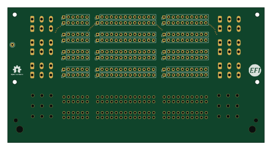
134pin 7-967288-1
139.7 × 73.7 mm38 parts2LGPL-3.01.2k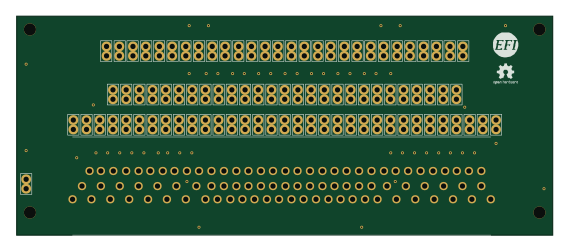
88 Pin Vag Breakout
142 × 58 mm91 parts2LGPL-3.01.2k
Rj45 breakout
rene-dev
15.2 × 53.8 mm3 parts2LGPL-3.0979