
Amiga Drawbridge FA2

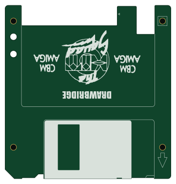
About the Amiga Drawbridge FA2 PCB
Amiga Drawbridge FA2 is an open source PCB design by tebl, published on GitHub. It is a 2-layer board measuring 90 × 94 mm, with 4 components from 1 distinct parts.
It belongs with the retro computing designs in this gallery.
From the project
A PCB build of Rob Smiths Amiga DrawBridge, an Arduino-based solution for reading and writing Amiga floppy disks on modern hardware. Also includes a version of Greaseweazle.
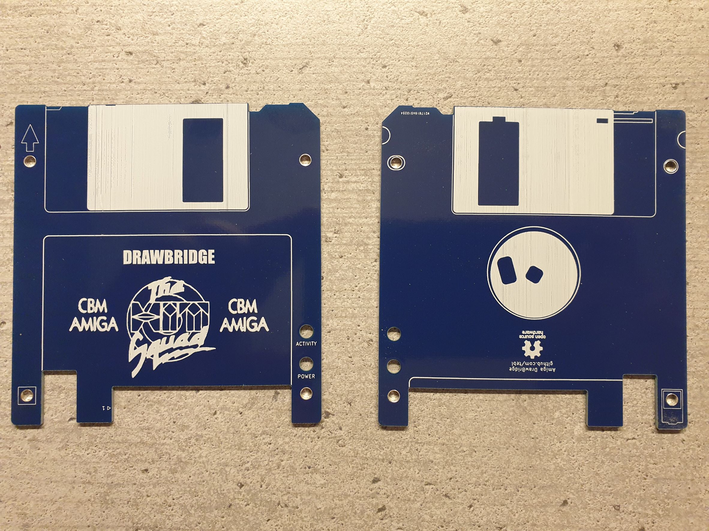
Amiga Drawbridge FA2 bill of materials (BOM)
4 components, 1 distinct parts.
| Qty | Part | Footprint | Refs |
|---|---|---|---|
| 4 | Mounting | M3_pin | M1, M2, M3, M4 |
Amiga Drawbridge FA2 design files
The KiCad project lives in the tebl/Amiga-DrawBridge repository on GitHub; these links point at the commit this page was built from.
Amiga Drawbridge FA2: common questions
How big is the Amiga Drawbridge FA2 PCB?
The Amiga Drawbridge FA2 measures 90 × 94 mm, has 2 copper layers and is 1.6 mm thick.
How many components are on the Amiga Drawbridge FA2?
4 components, from 1 distinct parts. The full bill of materials is listed on this page.
Where can I download the Amiga Drawbridge FA2 design files?
From the tebl/Amiga-DrawBridge repository on GitHub, which has the KiCad layout; the links under Design files point to each one.
Can I use the Amiga Drawbridge FA2 design in my own project?
The repository has no license, so all rights stay with tebl. Use it as a reference, and ask the author before reusing the design.
More boards in Amiga-DrawBridge
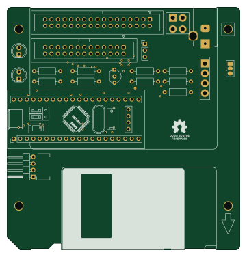 STM32
STM32Greaseweazle
90 × 94 mm25 parts2LNo license51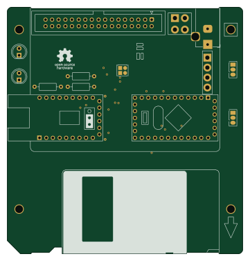 AVR/Arduino
Amiga Drawbridge
90 × 94 mm18 parts2LNo license51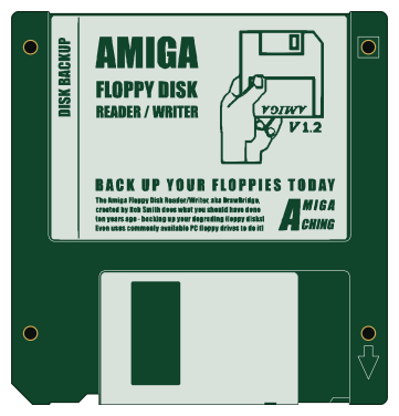
Amiga Drawbridge BA1
90 × 94 mm4 parts2LNo license51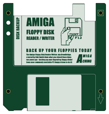
Amiga Drawbridge FA1
90 × 94 mm4 parts2LNo license51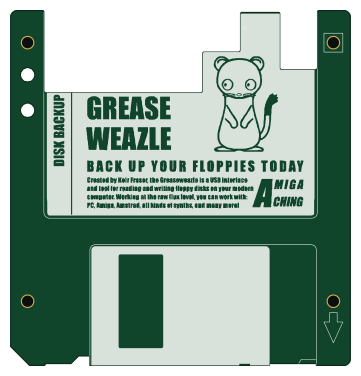
Greaseweazle FB1
90 × 94 mm4 parts2LNo license51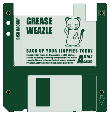
Greaseweazle FA1
90 × 94 mm4 parts2LNo license51
Similar boards
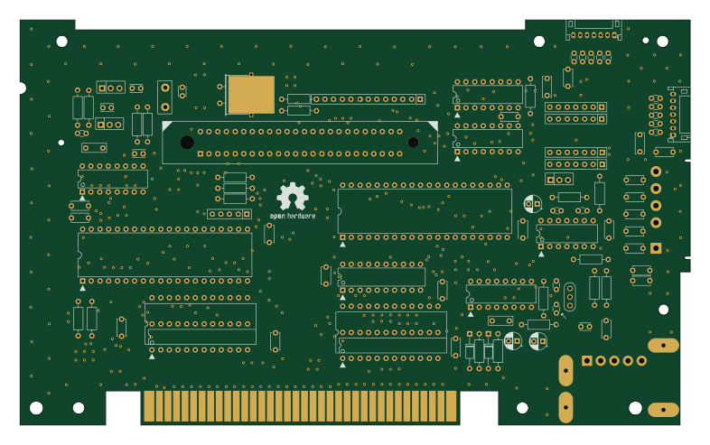
OpenTendo
Redherring32
196.3 × 118.7 mm93 parts2LTAPR-OHL-1.0850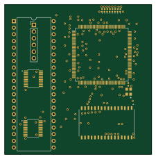
MCL86jr
MicroCoreLabs
56.1 × 57.1 mm66 parts4LNo license532
24pin flex interposer
Wren6991
29 × 32 mm3 parts2LNo license508
Sram dev board
50 × 50 mm12 parts2LNo license508
TRS-80 Color Computer 3
baldengineer
280 × 155.3 mm204 parts2LCC-BY-4.0442
Commodore Plus 4
284.7 × 158.9 mm212 parts2LCC-BY-4.0442