
CP2102 USB-UART Debug Adapter

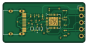
About the CP2102 USB-UART Debug Adapter PCB
CP2102 USB-UART Debug Adapter is an open source PCB design by tejashviraj19, published on GitHub. It is a 2-layer board measuring 31 × 15 mm, with 19 components from 9 distinct parts.
Other key parts include the CP2102N-Axx-xQFN28. By type, the board carries 7 resistors, 5 diodes, 4 capacitors, 2 connectors and 1 IC.
It belongs with the usb & debug tools designs in this gallery.
From the project
PCB Design projects, KiCad layouts, embedded hardware experiments, and fabrication-ready PCB designs.
A compact USB Type-C to UART Debug Adapter designed using KiCad and the CP2102 USB-to-UART Bridge Controller.
This project demonstrates the complete PCB design workflow including schematic capture, PCB layout, routing, Gerber generation, and 3D visualization.
- CP2102 USB-to-UART Bridge IC - USB Type-C Receptacle - TX LED - RX LED - ESD Protection Diodes - 5-Pin UART Header - Decoupling Capacitors - USB Configuration Resistors
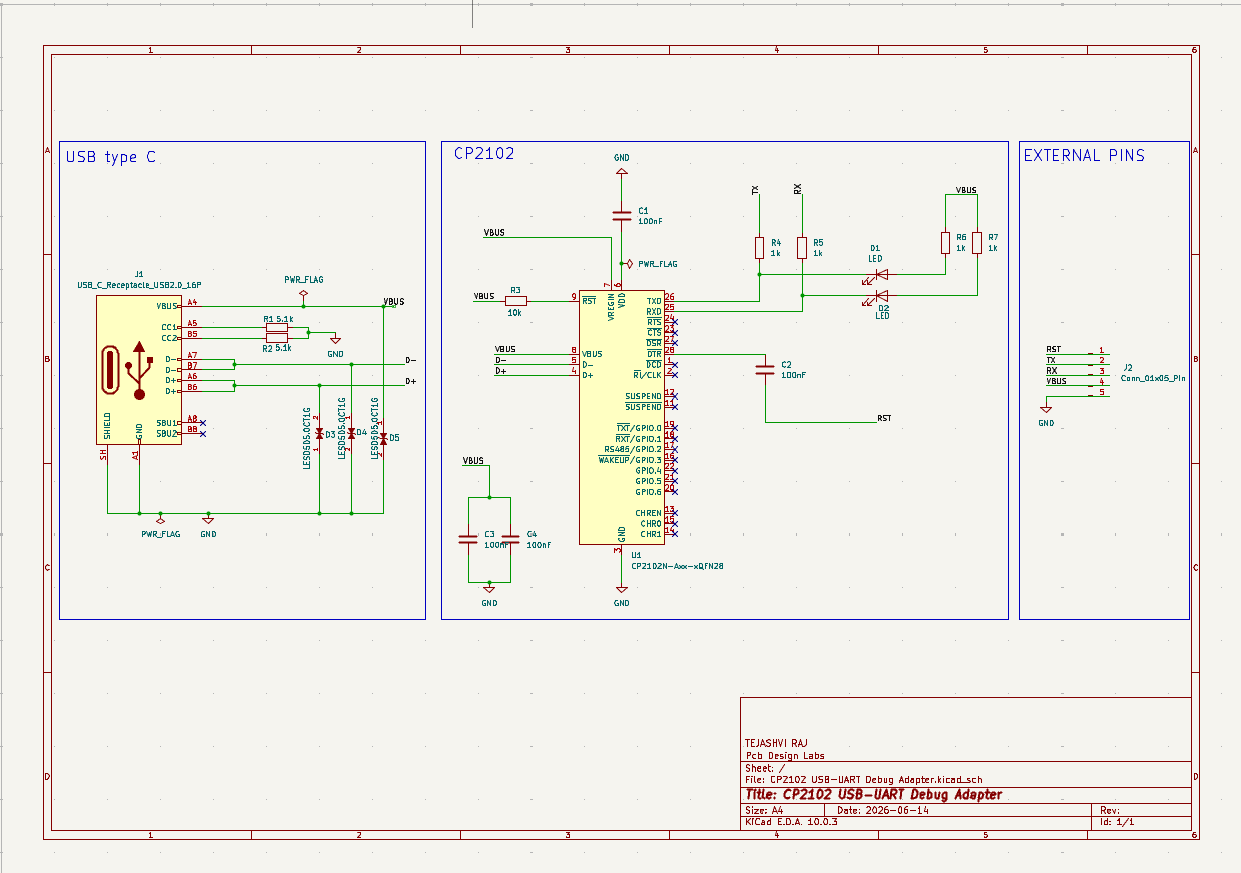
Main components on the CP2102 USB-UART Debug Adapter
CP2102 USB-UART Debug Adapter bill of materials (BOM)
19 components, 9 distinct parts.
| Qty | Part | Footprint | Refs |
|---|---|---|---|
| 1 | CP2102N-Axx-xQFN28 | QFN-28-1EP_5x5mm_P0.5mm_EP3.35x3.35mm | U1 |
| 1 | USB_C_Receptacle_USB2.0_16P | USB_C_Receptacle_HRO_TYPE-C-31-M-12 | J1 |
| 1 | Conn_01x05_Pin | PinHeader_1x05_P2.54mm_Horizontal | J2 |
| 2 | LED | LED_0201_0603Metric | D1, D2 |
| 3 | LESD5D5.0CT1G | TVS_LESD5D5.0CT1G | D3, D4, D5 |
| 4 | 100nF | C_0201_0603Metric | C1, C2, C3, C4 |
| 2 | 5.1K | R_0201_0603Metric | R1, R2 |
| 1 | 10K | R_0201_0603Metric | R3 |
| 4 | 1K | R_0201_0603Metric | R4, R5, R6, R7 |
CP2102 USB-UART Debug Adapter design files
The KiCad project lives in the tejashviraj19/PCB-Design-Lab repository on GitHub; these links point at the commit this page was built from.
CP2102 USB-UART Debug Adapter: common questions
How big is the CP2102 USB-UART Debug Adapter PCB?
The CP2102 USB-UART Debug Adapter measures 31 × 15 mm, has 2 copper layers and is 1.6 mm thick.
How many components are on the CP2102 USB-UART Debug Adapter?
19 components, from 9 distinct parts. The full bill of materials is listed on this page.
Where can I download the CP2102 USB-UART Debug Adapter design files?
From the tejashviraj19/PCB-Design-Lab repository on GitHub, which has the KiCad layout and the schematic; the links under Design files point to each one.
Can I use the CP2102 USB-UART Debug Adapter design in my own project?
The repository has no license, so all rights stay with tejashviraj19. Use it as a reference, and ask the author before reusing the design.
More boards in PCB-Design-Lab
Similar boards
XG Station Power
osy
54.3 × 91 mm9 parts2LCC-BY-4.0703
USB Hub Test
50 × 50 mm85 parts4LCC-BY-4.0703
FW-EC-DongleHiderPlus
LeoDJ
28.2 × 26.1 mm14 parts4LCERN-OHL-W-2.0490
Adapter tsop48
bbogush
48 × 33 mm3 parts2LGPL-3.0389
Adapter tsop48 solder
48 × 33 mm3 parts2LGPL-3.0389
Adapter soic8 solder
48 × 20 mm3 parts2LGPL-3.0389