
ModBus-RJ45-Breakout-2

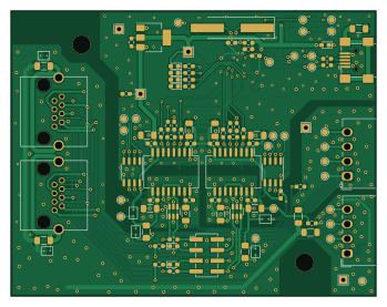
About the ModBus-RJ45-Breakout-2
ModBus-RJ45-Breakout-2 is an open source PCB design by the78mole, published on GitHub under the TAPR-OHL-1.0 license. It is a 2-layer board measuring 87 × 68 mm, with 116 components from 39 distinct parts.
Other key parts include the FT2232D, WE-TVS-82400102, MAX485E, ADM2687E and 93LC46B. By type, the board carries 37 capacitors, 37 resistors, 8 ICs, 8 connectors, 8 jumpers and 7 diodes.
It belongs with the dev boards & breakouts and usb & debug tools designs in this gallery.
From the project
The second iteration of the breakout with a Dual-USB-Serial-Converter (FT2232)
Here are some images of the first prototype, assembled with isolating RS485 transceivers. Echo already works, real testing on a ModBus will take place soon.
This repository includes an automated workflow that generates production-ready files for PCB manufacturing and assembly. The workflow creates:
- Gerber Files - Ready for PCB manufacturer submission - Drill Files - For via and hole drilling - Schematic PDF - Complete circuit documentation - Interactive BOM - HTML component placement guide - 3D STEP Model - For mechanical design verification - PCB Renders - Professional visualizations and…
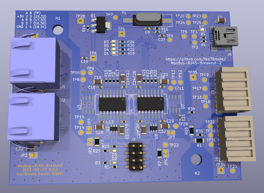
Main components on the ModBus-RJ45-Breakout-2
ModBus-RJ45-Breakout-2 bill of materials (BOM)
116 components, 39 distinct parts.
| Qty | Part | Footprint | Refs |
|---|---|---|---|
| 1 | FT2232D | LQFP-48_7x7mm_P0.5mm | U1 |
| 2 | WE-TVS-82400102 | SOT-23-6 | U2, U6 |
| 2 | MAX485E | SO-8_3.9x4.9mm_P1.27mm | U3, U7 |
| 2 | ADM2687E | SOIC-16W_7.5x12.8mm_P1.27mm | U4, U8 |
| 1 | 93LC46B | SOIC-8_3.9x4.9mm_P1.27mm | U5 |
| 1 | BSP250 | SOT-223 | Q1 |
| 1 | 6MHz | Crystal_SMD_HC49-SD_HandSoldering | Y1 |
| 2 | RJ45_Weidmueller_2562920000 | RJ45_Weidmüller_2562920000_Horizontal | J1, J2 |
| 1 | Bus_2 | Wago_734-164_1x04_P3.50mm_Horizontal | J3 |
| 1 | BUS_1 | Wago_734-164_1x04_P3.50mm_Horizontal | J4 |
| 1 | USB_B_Mini | USB_Mini-B_Wuerth_65100516121_Horizontal | J5 |
| 1 | 2X04 | PinHeader_2x04_P2.54mm_Vertical_SMD | J6 |
| 2 | 2734-104 WAGO 2734-104 WAGO | Dummy_0 | J7, J8 |
| 1 | 449-440-45 APRA 449-440-45 | Dummy_0 | DRA1 |
| 2 | 500mA | Fuse_1206_3216Metric_Pad1.42x1.75mm_HandSolder | F1, F2 |
| 1 | SH_GND_B | SolderJumper-2_P1.3mm_Open_TrianglePad1.0x1.5mm | JP1 |
| 1 | SH_GND_A | SolderJumper-2_P1.3mm_Open_TrianglePad1.0x1.5mm | JP2 |
| 4 | VCC_BR | SolderJumper-2_P1.3mm_Open_TrianglePad1.0x1.5mm | JP3, JP4, JP6, JP7 |
| 2 | GND_BR | SolderJumper-2_P1.3mm_Open_TrianglePad1.0x1.5mm | JP5, JP8 |
| 5 | Probe | TestPoint_THTPad_2.0x2.0mm_Drill1.0mm | TP1, TP6, TP28, TP34, TP35 |
Show 19 more
| Qty | Part | Footprint | Refs |
|---|---|---|---|
| 4 | green | LED_0603_1608Metric_Pad1.05x0.95mm_HandSolder | D1, D2, D3, D6 |
| 2 | yellow | LED_0603_1608Metric_Pad1.05x0.95mm_HandSolder | D4, D5 |
| 1 | red | LED_0603_1608Metric_Pad1.05x0.95mm_HandSolder | D7 |
| 1 | FB | R_0603_1608Metric_Pad0.98x0.95mm_HandSolder | L2 |
| 5 | 1n | C_1206_3216Metric_Pad1.33x1.80mm_HandSolder | C1, C31, C32, C33, C34 |
| 1 | 4u7 | C_1206_3216Metric_Pad1.33x1.80mm_HandSolder | C2 |
| 21 | 100n | C_0603_1608Metric_Pad1.08x0.95mm_HandSolder | C3, C6, C7, C8, C9, C10, C11, C12 +13 |
| 2 | 27p | C_0603_1608Metric_Pad1.08x0.95mm_HandSolder | C4, C5 |
| 8 | 10u | C_1206_3216Metric_Pad1.33x1.80mm_HandSolder | C13, C16, C17, C20, C23, C26, C27, C30 |
| 2 | 0 | R_1206_3216Metric_Pad1.30x1.75mm_HandSolder | R1, R16 |
| 8 | np | R_0603_1608Metric_Pad0.98x0.95mm_HandSolder | R2, R8, R10, R12, R14, R33, R34, R35 |
| 8 | 1K | R_0603_1608Metric_Pad0.98x0.95mm_HandSolder | R3, R13, R19, R20, R24, R25, R29, R32 |
| 10 | 27 | R_0603_1608Metric_Pad0.98x0.95mm_HandSolder | R4, R6, R15, R17, R18, R21, R22, R23 +2 |
| 2 | 120 | R_0603_1608Metric_Pad0.98x0.95mm_HandSolder | R5, R28 |
| 2 | 1K5 | R_0603_1608Metric_Pad0.98x0.95mm_HandSolder | R7, R9 |
| 1 | 470 | R_0603_1608Metric_Pad0.98x0.95mm_HandSolder | R11 |
| 1 | 2K2 | R_0603_1608Metric_Pad0.98x0.95mm_HandSolder | R26 |
| 1 | 10K | R_0603_1608Metric_Pad0.98x0.95mm_HandSolder | R27 |
| 2 | 0 | R_0603_1608Metric_Pad0.98x0.95mm_HandSolder | R30, R31 |
ModBus-RJ45-Breakout-2 design files
The KiCad project lives in the the78mole/ModBus-RJ45-Breakout-2 repository on GitHub; these links point at the commit this page was built from.
- LayoutModbus-RJ45-Breakout.kicad_pcb
- SchematicModbus-RJ45-Breakout.kicad_sch
ModBus-RJ45-Breakout-2: common questions
How big is the ModBus-RJ45-Breakout-2?
The ModBus-RJ45-Breakout-2 measures 87 × 68 mm, has 2 copper layers and is 1.6 mm thick.
How many components are on the ModBus-RJ45-Breakout-2?
116 components, from 39 distinct parts. The full bill of materials is listed on this page.
Where can I download the ModBus-RJ45-Breakout-2 design files?
From the the78mole/ModBus-RJ45-Breakout-2 repository on GitHub, which has the KiCad layout and the schematic; the links under Design files point to each one.
Can I use the ModBus-RJ45-Breakout-2 design in my own project?
Yes, under the terms of its TAPR-OHL-1.0 license, which the78mole chose for the repository.
Similar boards
88 Pin Vag Breakout
rusefi
142 × 58 mm91 parts2LGPL-3.01.2k
134pin 7-967288-1
139.7 × 73.7 mm38 parts2LGPL-3.01.2k
Breakout 60pin EEC-IV
139.7 × 62.2 mm15 parts2LGPL-3.01.2k
Breakout 112pin Connector
174 × 58 mm39 parts2LGPL-3.01.2k
Eecv breakout
140.8 × 53.7 mm9 parts4LGPL-3.01.2k
Rj45 breakout
rene-dev
15.2 × 53.8 mm3 parts2LGPL-3.0979