
Reciever

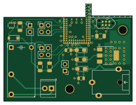
About the Reciever PCB
Reciever is an open source PCB design by TheTosters, published on GitHub under the BSD-3-Clause license. It is a 2-layer board measuring 48.5 × 36.8 mm, with 20 components from 17 distinct parts.
Other key parts include the DDC114EU, BL654 and AMS1117-3.3. By type, the board carries 5 connectors, 5 capacitors, 3 ICs, 3 resistors, 2 diodes and 1 relay.
It belongs with the sensors designs in this gallery.
From the project
Multi node heater control on Nordic BTLE
You also need nrfprog tools and small patch for SDK from CMSIS. But this is handled by
This is super-glue solution, so your eyes will bleeed... It will use host compiler (not cross-compiler) to build host based tests. It is NOT ment to test all, only most complicated logic. So to have test build and run you have to:
Main components on the Reciever
Reciever bill of materials (BOM)
20 components, 17 distinct parts.
| Qty | Part | Footprint | Refs |
|---|---|---|---|
| 1 | DDC114EU | SOT-363_SC-70-6 | U1 |
| 1 | BL654 | BL654 | U2 |
| 1 | AMS1117-3.3 | SOT-223-3_TabPin2 | U3 |
| 1 | UART | PinHeader_1x02_P2.54mm_Vertical | J1 |
| 1 | BTN | PinHeader_2x02_P2.54mm_Vertical | J2 |
| 1 | OLED | PinHeader_2x02_P2.54mm_Vertical | J3 |
| 1 | HEATER_CON | TerminalBlock_TE_282834-2_1x02_P2.54mm_Horizontal | J4 |
| 1 | PWR-9V | 1613-18 | J5 |
| 1 | RM50-xx21 | Relay_SPST_Finder_32.21-x300 | K1 |
| 1 | RESET | R_1206_3216Metric | SW1 |
| 1 | 1N5819HW-7-F | D_SOD-123 | D1 |
| 1 | LED | PinHeader_1x02_P2.54mm_Vertical | D2 |
| 2 | 10uF | CP_EIA-3216-12_Kemet-S_Pad1.58x1.35mm_HandSolder | C1, C3 |
| 2 | 100n | C_0805_2012Metric | C2, C5 |
| 1 | 22uF | CP_EIA-3216-12_Kemet-S_Pad1.58x1.35mm_HandSolder | C4 |
| 2 | 4,7k | R_1206_3216Metric | R1, R2 |
| 1 | 33 | R_1206_3216Metric | R3 |
Reciever design files
The KiCad project lives in the TheTosters/HeaterControl repository on GitHub; these links point at the commit this page was built from.
Reciever: common questions
How big is the Reciever PCB?
The Reciever measures 48.5 × 36.8 mm, has 2 copper layers and is 1.6 mm thick.
How many components are on the Reciever?
20 components, from 17 distinct parts. The full bill of materials is listed on this page.
Where can I download the Reciever design files?
From the TheTosters/HeaterControl repository on GitHub, which has the KiCad layout; the links under Design files point to each one.
Can I use the Reciever design in my own project?
Yes, under the terms of its BSD-3-Clause license, which TheTosters chose for the repository.
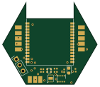
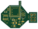
More boards in HeaterControl
Similar boards
Sensor smd
scottbez1
40 × 20 mm5 parts2LApache-2.04.2k
Sensors
StuckAtPrototype
15.2 × 9 mm14 parts4LApache-2.03.8k
Microphone
Mentra-Community
5.5 × 6.1 mm6 parts2LMIT1.2k
TemperaturePCB PANEL
stuartpittaway
116 × 75.5 mm178 parts2LCC-BY-NC-4.01.1k
Pots
shanteacontrols
390 × 93 mm75 parts2LApache-2.0956
USB
52 × 12.6 mm6 parts2LApache-2.0956