
TT04+ FPGA ASIC Simulator

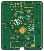
About the TT04+ FPGA ASIC Simulator PCB
TT04+ FPGA ASIC Simulator is an open source FPGA PCB design by TinyTapeout, published on GitHub under the Apache-2.0 license. It is a 4-layer board measuring 45 × 52.5 mm, with 77 components from 28 distinct parts.
Its main chip is the ICE40UP5K-SG48I, from the FPGA family. Other key parts include the AP2112K-3.3TRG1, AP2112K-1.2TRG1 and W25Q32JVSSIQ. By type, the board carries 30 resistors, 28 capacitors, 5 diodes, 4 ICs, 4 connectors and 3 switches.
It belongs with the dev boards & breakouts designs in this gallery.
From the project
Tiny Tapeout breakout PCBs
The Tiny Tapeout chips are delivered on a breakout board that allows:
* the demo board to host and interact with the IC and its projects
* easily moving the ASIC to other more specialized PCBs
The PCBs are keyed such that direction of insertion onto hosts is made clear.
Versionning has been refactored such that we only have a single directory, moving forward, which will always be the latest iteration of the breakout board. Prior versions are tagged and all available here.
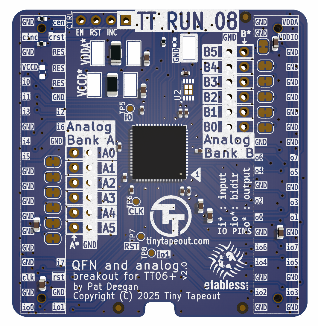
Main components on the TT04+ FPGA ASIC Simulator
TT04+ FPGA ASIC Simulator bill of materials (BOM)
77 components, 28 distinct parts — part numbers from the project's BOM.
| Qty | Part | Footprint | Refs |
|---|---|---|---|
| 1 | AP2112K-3.3TRG1 AP2112K-3.3 | SOT-23-5 | U1 |
| 1 | AP2112K-1.2TRG1 AP2112K-1.2 | SOT-23-5 | U2 |
| 1 | ICE40UP5K-SG48I ICE40UP5K-SG48ITR | QFN-48-1EP_7x7mm_P0.5mm_EP5.6x5.6mm | U3 |
| 1 | W25Q32JVSSIQ W25Q32JVSS | SOIC-8_5.23x5.23mm_P1.27mm | U4 |
| 1 | KC2520Z24.0000C1KX00 24MHz | Oscillator_SMD_ECS_2520MV-xxx-xx-4Pin_2.5x2.0mm | X1 |
| 2 | NPTC202KFMS-RC ~ | FH-00148_PinSocket_2x20_P2.54mm | CON1, CON2 |
| 1 | USB-TYPE-C-019 USB_C | USB_C_Receptacle_HRO_TYPE-C-31-M-12 | J1 |
| 1 | Conn_02x04_Odd_Even | PinHeader_2x04_P2.54mm_Vertical_SMD | J2 |
| 1 | 0ZCK0035FF2G 350mA | Fuse_0805_2012Metric | F1 |
| 3 | 434121025816 | 434121025816 | SW1, SW2, SW3 |
| 2 | 0603ESDA-AEC1 TVS | D_0603_1608Metric | D1, D4 |
| 1 | 1N4448WT | D_SOD-523 | D2 |
| 1 | PESD36VS1UL,315 VBUSTVS | DFN1006-2 | D3 |
| 1 | EAST1616RGBB4 RGB | LED_EAST1616RGBA3 | D5 |
| 1 | MFBM1V1608-121-R 120R | L_0603_1608Metric | FB1 |
| 1 | CUSBSHIELD | C_0603_1608Metric | C1 |
| 7 | GRT188R61H105KE13D C_1u_0603_50V | C_0603_1608Metric | C2, C4, C5, C8, C11, C12, C13 |
| 11 | GRM155R71H104KE14J C_100n_0402_50V | C_0402_1005Metric | C3, C7, C16, C17, C18, C20, C21, C23 +3 |
| 7 | GRM188R61E475KE11D C_4p7u_0603_25V | C_0603_1608Metric | C6, C10, C15, C19, C22, C25, C29 |
| 2 | CL05B331KB5NNNC C_330p_0402_50V | C_0402_1005Metric | C9, C14 |
Show 8 more
| Qty | Part | Footprint | Refs |
|---|---|---|---|
| 1 | CRGCQ0603F1M0 R_1M_0603 | R_0603_1608Metric | R1 |
| 3 | RC0402FR-07100RL R_100R_0402 | R_0402_1005Metric | R2, R10, R14 |
| 2 | CR0402-FX-5101GLF R_5k1_0402 | R_0402_1005Metric | R3, R7 |
| 4 | CR0402-FX-1501GLF R_1k5_0402 | R_0402_1005Metric | R4, R9, R15, R20 |
| 4 | CR0402-FX-68R0GLF R_68R_0402 | R_0402_1005Metric | R5, R6, R11, R12 |
| 9 | ERJ-U02F1002X R_10k_0402 | R_0402_1005Metric | R8, R13, R16, R17, R18, R21, R24, R26 +1 |
| 6 | CRG0603ZR R_0R_0603_JUMPER | R_0603_1608Metric | R19, R22, R23, R25, R28, R30 |
| 1 | RC0402FR-0710KL R_10k_0402 | R_0402_1005Metric | R31 |
TT04+ FPGA ASIC Simulator design files
The KiCad project lives in the TinyTapeout/breakout-pcb repository on GitHub; these links point at the commit this page was built from.
TT04+ FPGA ASIC Simulator: common questions
What microcontroller does the TT04+ FPGA ASIC Simulator use?
The TT04+ FPGA ASIC Simulator is built around the ICE40UP5K-SG48I, from the FPGA family.
How big is the TT04+ FPGA ASIC Simulator PCB?
The TT04+ FPGA ASIC Simulator measures 45 × 52.5 mm, has 4 copper layers and is 1.6 mm thick.
How many components are on the TT04+ FPGA ASIC Simulator?
77 components, from 28 distinct parts, with part numbers taken from the project's own BOM. The full bill of materials is listed on this page.
Where can I download the TT04+ FPGA ASIC Simulator design files?
From the TinyTapeout/breakout-pcb repository on GitHub, which has the KiCad layout, the schematic and the BOM; the links under Design files point to each one.
Can I use the TT04+ FPGA ASIC Simulator design in my own project?
Yes, under the terms of its Apache-2.0 license, which TinyTapeout chose for the repository.
Can I test firmware for the TT04+ FPGA ASIC Simulator without the hardware?
Yes. HardLabs builds a simulation of the board from its netlist and BOM, so you can run and debug FPGA firmware against it before you order a PCB.
More boards in breakout-pcb
 FPGA
TinyTapeout ASIC Simulator (for TT3)
45 × 52.5 mm72 parts2LApache-2.021
QFN Breakout For TinyTapeout Skywater ASICs
50 × 50 mm47 parts4LApache-2.021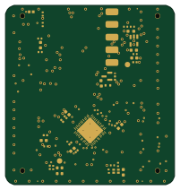 FPGA
Tt06-fpga-ICE40UP5k
50 × 53 mm44 parts4LApache-2.021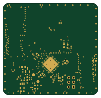 FPGA
Ttdbv3-fpga-ICE40UP5k
50 × 48 mm41 parts4LApache-2.021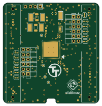
Tiny Tapeout 06+ Breakout QFN
50 × 52 mm37 parts2LApache-2.021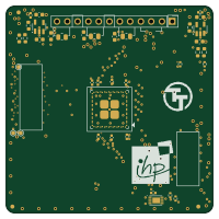
QFN Breakout For TinyTapeout IHP ASICs
50 × 50 mm37 parts4LApache-2.021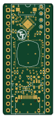 WCH CH32/CH55x
CoB DIP Breakout
19 × 42.1 mm33 parts4LApache-2.021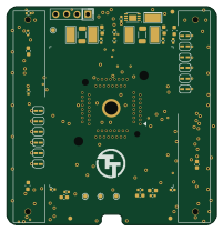
Breakout tt06-qfn socket
50 × 52 mm32 parts2LApache-2.021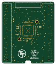
Breakout tt04-qfn socket
45 × 52.5 mm13 parts2LApache-2.021
Similar boards
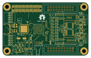 FPGA
Base board
GlasgowEmbedded
80 × 49 mm222 parts4L0BSD2.2k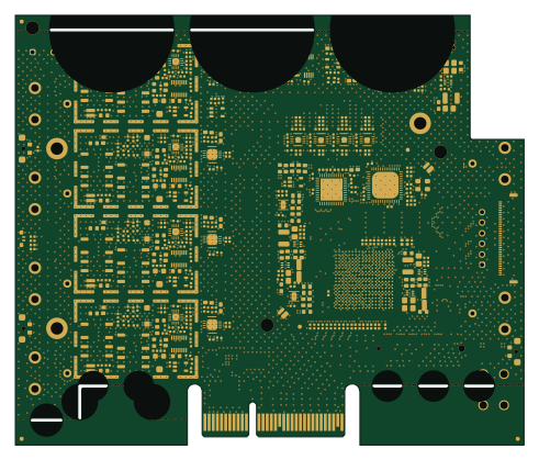 FPGA
Thunderscope Rev5.3
EEVengers
122.5 × 103.5 mm817 parts6LMIT1.3k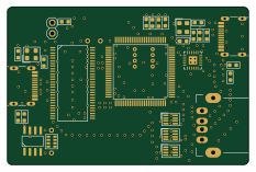 FPGA
Usb sniffer
ataradov
58.2 × 38.1 mm86 parts2LBSD-3-Clause1.3k FPGA
Tomu, I'm
theacodes
13 × 9.4 mm40 parts4LMIT1.1k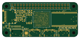 FPGA
Icepi zero
cheyao
65 × 30 mm143 parts4LSHL-2.1828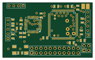 FPGA
Gcvideo
ikorb
49 × 30 mm44 parts4LNo license765