
Sensor conditioning

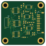
About the Sensor conditioning PCB
Sensor conditioning is an open source PCB design by UVicRocketry, published on GitHub. It is a 4-layer board measuring 38 × 38 mm, with 30 components from 9 distinct parts.
Other key parts include the max4208aua+t and MCP4161-103E/SN. By type, the board carries 18 resistors, 6 ICs, 4 capacitors and 2 connectors.
It belongs with the sensors designs in this gallery.
From the project
A3-Sensors-DAQ This is a repository for Anduril 3's Sensors and Data Acquisition system. This repository contains files for both PCB hardware and STM32 software. ## Repository structure The repository has the following structure: ROOT | Flight Code | ---- Platformio | --------src
A3-Sensors-DAQ This is a repository for Anduril 3's Sensors and Data Acquisition system. This repository contains files for both PCB hardware and STM32 software. ## Repository structure The repository has the following structure: ROOT | Flight Code | ---- Platformio | --------src | ------------ system (autogenerated from STM32 CubeMX) | ------------ tasks (custom code) | Flight Hardware (KiCad project for flight hardware) | Software Development (any testing or data analysis scripts) | Hardware Development (breakout boards) | ---- Transceiver | ---- ADC | Release Notes (all features currently…
Main components on the Sensor conditioning
Sensor conditioning bill of materials (BOM)
30 components, 9 distinct parts — part numbers from the project's BOM.
| Qty | Part | Footprint | Refs |
|---|---|---|---|
| 3 | max4208aua+t | 21-0036K_MXM | U1, U2, U3 |
| 3 | MCP4161-103E/SN | SOIC8-N_MC_MCH | U4, U5, U6 |
| 1 | 5034801400 | CON_5034801400_MOL | J1 |
| 1 | S10B-ZR-SM4A-TFLFSN | CONN10_S10B-ZR-SM4A-TF_JST | J2 |
| 1 | 10uF | C_0603_1608Metric_Pad1.08x0.95mm_HandSolder | C1 |
| 3 | 1nF | C_0603_1608Metric_Pad1.08x0.95mm_HandSolder | C2, C3, C4 |
| 6 | 5K | R_0603_1608Metric_Pad0.98x0.95mm_HandSolder | R1, R2, R3, R10, R11, R12 |
| 9 | 360 | R_0603_1608Metric_Pad0.98x0.95mm_HandSolder | R4, R5, R6, R7, R8, R9, R16, R17 +1 |
| 3 | 1K | R_0603_1608Metric_Pad0.98x0.95mm_HandSolder | R13, R14, R15 |
Sensor conditioning design files
The KiCad project lives in the UVicRocketry/A3-Sensors-DAQ repository on GitHub; these links point at the commit this page was built from.
Sensor conditioning: common questions
How big is the Sensor conditioning PCB?
The Sensor conditioning measures 38 × 38 mm, has 4 copper layers and is 1.6 mm thick.
How many components are on the Sensor conditioning?
30 components, from 9 distinct parts, with part numbers taken from the project's own BOM. The full bill of materials is listed on this page.
Where can I download the Sensor conditioning design files?
From the UVicRocketry/A3-Sensors-DAQ repository on GitHub, which has the KiCad layout, the schematic and the BOM; the links under Design files point to each one.
Can I use the Sensor conditioning design in my own project?
The repository has no license, so all rights stay with UVicRocketry. Use it as a reference, and ask the author before reusing the design.
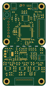
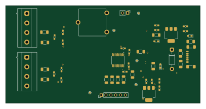
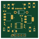
More boards in A3-Sensors-DAQ
Similar boards
Sensor smd
scottbez1
40 × 20 mm5 parts2LApache-2.04.2k
Sensors
StuckAtPrototype
15.2 × 9 mm14 parts4LApache-2.03.8k
Microphone
Mentra-Community
5.5 × 6.1 mm6 parts2LMIT1.2k
TemperaturePCB PANEL
stuartpittaway
116 × 75.5 mm178 parts2LCC-BY-NC-4.01.1k
Pots
shanteacontrols
390 × 93 mm75 parts2LApache-2.0956
USB
52 × 12.6 mm6 parts2LApache-2.0956