
Murmulator.1010

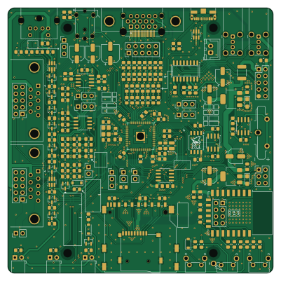
About the Murmulator.1010 PCB
Murmulator.1010 is an open source RP2040/RP2350 PCB design by UzixLS, published on GitHub. It is a 2-layer board measuring 100 × 100 mm, with 191 components from 65 distinct parts.
Its main chip is the RP2350B, from the RP2040/RP2350 family. Other key parts include the 1117-3.3, DS3231MZ, ESP-PSRAM64H, W25Q128JVSIQ and ESP-12F. By type, the board carries 93 resistors, 48 capacitors, 14 connectors, 13 ICs, 10 transistors and 5 diodes.
It belongs with the audio and power & battery designs in this gallery.
From the project
10x10cm version of https://murmulator.ru - Raspberry Pico-based hardware emulator platform
Technical specs: - Compatible with the Murmulator M2P2 and Frank PGA projects - HDMI and VGA video outputs - CVBS composite video + audio output via 3.5mm jack connector - PWM and I2S (TDA1387T DAC) audio output with LMV358 opamp - Combined PS/2 keyboard and mouse port - Two DB-9 ports for Famicom (Dendy)-compatible joysticks - Two external USB-host ports and two internal connectors via an MW7211A hub - USB Type-C power supply and programming - RP2350B MCU in a QFN-80 package - 16MB SPI flash (W25Q128) - Two PSRAM chips: SPI + QSPI - RTC (DS3231MZ) with battery - ESP8266 WiFi module (ESP-01…
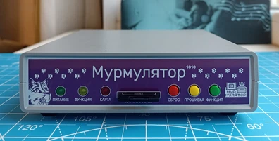
Main components on the Murmulator.1010
Murmulator.1010 bill of materials (BOM)
191 components, 65 distinct parts.
| Qty | Part | Footprint | Refs |
|---|---|---|---|
| 2 | 1117-3.3 | SOT-223-3_TabPin2 | U1, U2 |
| 1 | RP2350B | QFN-80-1EP_10x10mm_P0.4mm_EP3.4x3.4mm | U3 |
| 1 | DS3231MZ | SOIC-8_3.9x4.9mm_P1.27mm | U4 |
| 1 | ESP-PSRAM64H | SOIC-8_3.9x4.9mm_P1.27mm | U5 |
| 1 | W25Q128JVSIQ | SOIC-8_5.3x5.3mm_P1.27mm | U7 |
| 1 | ESP-12F | ESP-12E | U8 |
| 1 | MW7211A | SOP-16_4.4x10.4mm_P1.27mm | U9 |
| 1 | TDA1387T | SO-8_3.9x4.9mm_P1.27mm | U10 |
| 1 | LMV358 | SOIC-8_3.9x4.9mm_P1.27mm | U11 |
| 3 | IP4220CZ6 | SC-74-6_1.55x2.9mm_P0.95mm | U12, U13, U14 |
| 1 | BC817 | SOT-23 | Q1 |
| 1 | BC856 | SOT-23 | Q2 |
| 8 | BSS138 | SOT-23 | Q3, Q4, Q5, Q6, Q7, Q8, Q9, Q10 |
| 1 | ABM8-272-T3 | Crystal_SMD_3225-4Pin_3.2x2.5mm_HandSoldering | Y1 |
| 1 | PJ-392 | PinHeader_1x03_P2.54mm_Vertical | J1 |
| 1 | TE 041021-4 | SD_TE_2041021-mod | J3 |
| 1 | Conn_02x03_Odd_Even | PinHeader_2x03_P2.54mm_Vertical | J6 |
| 1 | Mini-DIN-6 | minidin-6 | J7 |
| 2 | USB_A | USB_A_Wuerth_614004134726_Horizontal | J8, J11 |
| 4 | Conn_02x05_Odd_Even | PinHeader_2x05_P2.54mm_Vertical | J9, J12, J17, J18 |
Show 45 more
| Qty | Part | Footprint | Refs |
|---|---|---|---|
| 1 | B2B-XH-A | JST_XH_B2B-XH-A_1x02_P2.50mm_Vertical | J14 |
| 1 | USB Type C | USB_C_Receptacle_HRO_TYPE-C-31-M-12_dangling | J19 |
| 1 | HDMI_A | HDMI_A_Molex_208658-1001_Horizontal | J20 |
| 1 | PJ-322 | PJ-322 | J21 |
| 1 | 1775485-1 or S8401-46 | CR2032V | BT1 |
| 1 | 1A | Fuse_1812_4532Metric_Pad1.30x3.40mm_HandSolder | F1 |
| 1 | G738 or G706 | g738-g706 | N1 |
| 3 | Push angle button, 6x6x7mm or 6x6x8mm | SW_Tactile_SPST_Angled_PTS645Vx58-2LFS | SW1, SW2, SW3 |
| 2 | 1N4148W | D_SOD-123 | D1, D2 |
| 1 | LED_Red | LED_D5.0mm_Horizontal_O1.27mm_Z3.0mm | D3 |
| 1 | LED_Yellow | LED_D5.0mm_Horizontal_O1.27mm_Z3.0mm | D4 |
| 1 | LED_Green | LED_D5.0mm_Horizontal_O1.27mm_Z3.0mm | D5 |
| 1 | AOTA-B201610S3R3-101-T | L_1008_2520Metric | L1 |
| 6 | 100u | CP_Elec_5x5.9 | C1, C12, C19, C26, C48, C49 |
| 9 | 10u | C_0805_2012Metric_Pad1.18x1.45mm_HandSolder | C2, C4, C5, C8, C22, C29, C31, C44 +1 |
| 3 | 4.7u | C_0805_2012Metric_Pad1.18x1.45mm_HandSolder | C3, C9, C18 |
| 2 | 15p | C_0805_2012Metric_Pad1.18x1.45mm_HandSolder | C6, C7 |
| 17 | 1u | C_0805_2012Metric_Pad1.18x1.45mm_HandSolder | C10, C11, C13, C16, C17, C21, C23, C24 +9 |
| 2 | 22u | CP_EIA-3216-18_Kemet-A_HandSolder | C14, C28 |
| 1 | 100n | C_0805_2012Metric_Pad1.18x1.45mm_HandSolder | C15 |
| 1 | 10n | C_0805_2012Metric_Pad1.18x1.45mm_HandSolder | C20 |
| 1 | 220u | CP_Elec_6.3x7.7 | C38 |
| 4 | 4.7n | C_0805_2012Metric_Pad1.18x1.45mm_HandSolder | C39, C40, C42, C43 |
| 2 | 1.5n | C_0805_2012Metric_Pad1.18x1.45mm_HandSolder | C46, C47 |
| 20 | 4.7k | R_0805_2012Metric_Pad1.20x1.40mm_HandSolder | R1, R2, R12, R13, R25, R28, R29, R30 +12 |
| 10 | 10k | R_0805_2012Metric_Pad1.20x1.40mm_HandSolder | R3, R9, R11, R18, R19, R22, R23, R24 +2 |
| 2 | 470 | R_0805_2012Metric_Pad1.20x1.40mm_HandSolder | R4, R54 |
| 4 | 27 | R_0805_2012Metric_Pad1.20x1.40mm_HandSolder | R5, R14, R15, R16 |
| 13 | 1k | R_0805_2012Metric_Pad1.20x1.40mm_HandSolder | R6, R7, R8, R21, R57, R58, R59, R61 +5 |
| 1 | 470k | R_0805_2012Metric_Pad1.20x1.40mm_HandSolder | R10 |
| 2 | 220 | R_0805_2012Metric_Pad1.20x1.40mm_HandSolder | R17, R20 |
| 1 | 750 | R_0805_2012Metric_Pad1.20x1.40mm_HandSolder | R32 |
| 14 | 270 | R_0805_2012Metric_Pad1.20x1.40mm_HandSolder | R33, R34, R35, R36, R37, R38, R83, R84 +6 |
| 5 | 150 | R_0805_2012Metric_Pad1.20x1.40mm_HandSolder | R39, R40, R41, R42, R43 |
| 1 | 300 | R_0805_2012Metric_Pad1.20x1.40mm_HandSolder | R44 |
| 1 | 100k | R_0805_2012Metric_Pad1.20x1.40mm_HandSolder | R46 |
| 1 | 51 | R_0805_2012Metric_Pad1.20x1.40mm_HandSolder | R47 |
| 1 | 0 | R_0805_2012Metric_Pad1.20x1.40mm_HandSolder | R51 |
| 2 | 2k | R_0805_2012Metric_Pad1.20x1.40mm_HandSolder | R55, R56 |
| 3 | 330 | R_0805_2012Metric_Pad1.20x1.40mm_HandSolder | R60, R62, R64 |
| 2 | 100 | R_0805_2012Metric_Pad1.20x1.40mm_HandSolder | R65, R66 |
| 2 | 2.2k | R_0805_2012Metric_Pad1.20x1.40mm_HandSolder | R69, R72 |
| 4 | 47k | R_0805_2012Metric_Pad1.20x1.40mm_HandSolder | R75, R76, R93, R94 |
| 2 | 2.7k | R_0805_2012Metric_Pad1.20x1.40mm_HandSolder | R81, R82 |
| 2 | 5.1k | R_0805_2012Metric_Pad1.20x1.40mm_HandSolder | R91, R92 |
Murmulator.1010 design files
The KiCad project lives in the UzixLS/murmulator1010-board repository on GitHub; these links point at the commit this page was built from.
Murmulator.1010: common questions
What microcontroller does the Murmulator.1010 use?
The Murmulator.1010 is built around the RP2350B, from the RP2040/RP2350 family.
How big is the Murmulator.1010 PCB?
The Murmulator.1010 measures 100 × 100 mm, has 2 copper layers and is 1.6 mm thick.
How many components are on the Murmulator.1010?
191 components, from 65 distinct parts. The full bill of materials is listed on this page.
Where can I download the Murmulator.1010 design files?
From the UzixLS/murmulator1010-board repository on GitHub, which has the KiCad layout and the schematic; the links under Design files point to each one.
Can I use the Murmulator.1010 design in my own project?
The repository has no license, so all rights stay with UzixLS. Use it as a reference, and ask the author before reusing the design.
Can I test firmware for the Murmulator.1010 without the hardware?
Yes. HardLabs builds a simulation of the board from its netlist and BOM, so you can run and debug RP2040/RP2350 firmware against it before you order a PCB.
Similar boards
 RP2040/RP2350
OSO-BOOK-C1
joeycastillo
85 × 115 mm29 parts2LCC-BY-SA-4.08.1k RP2040/RP2350
Corne cherry
foostan
277.2 × 107.5 mm164 parts2LCC-BY-4.07.7k RP2040/RP2350
Corne chocolate
277.2 × 107.5 mm164 parts2LCC-BY-4.07.7k RP2040/RP2350
Jitx design
gusmanb
55.5 × 65 mm26 parts4LGPL-3.05.0k RP2040/RP2350
LogicAnalyzer
57 × 55.2 mm6 parts2LGPL-3.05.0k RP2040/RP2350
Main
google
98 × 71 mm102 parts2LApache-2.02.9k