
3ChannelCCdriver panelized

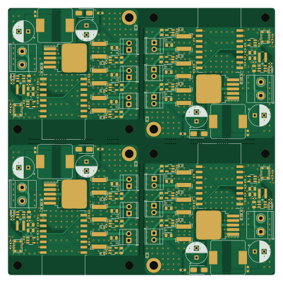
About the 3ChannelCCdriver panelized PCB
3ChannelCCdriver panelized is an open source ESP8266 PCB design by wszeto9, published on GitHub. It is a 2-layer board measuring 100 × 100 mm, with 58 components from 32 distinct parts.
Its main chip is the ESP-12F, from the ESP8266 family. Other key parts include the AL8860WT-7, TPS54202DDCR, XL6019 and XC6210B332MR. By type, the board carries 21 capacitors, 16 resistors, 7 ICs, 5 connectors, 5 inductors and 4 diodes.
It belongs with the iot & wireless designs in this gallery.
From the project
Powers a 100W RGB COB Led with Constant Current Driving
- Follow the iBOM and solder all items onto the board. - Attach the programming device onto the mezzamine connector on the top left of the board - Program the ESP8266 with WLED - Setup WLED with a single analog RGB channel attached to it. The pinouts should be: - Green: GPIO 13 - Red: GPIO 12 - Blue: GPIO 14 - Unplug the programming header and attach the LED and a 24V/5A power supply to the screw terminals - Connect to the ESP's Wi-Fi network and turn on the lights!
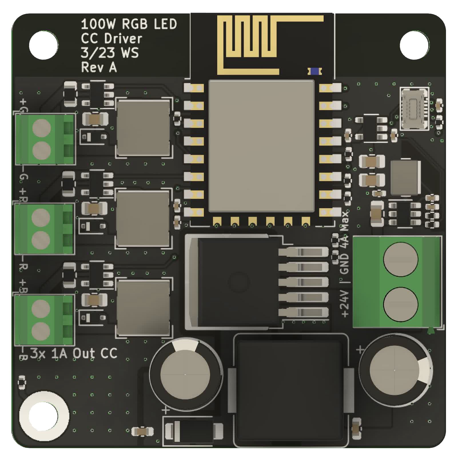
Main components on the 3ChannelCCdriver panelized
3ChannelCCdriver panelized bill of materials (BOM)
58 components, 32 distinct parts.
| Qty | Part | Footprint | Refs |
|---|---|---|---|
| 3 | AL8860WT-7 | TSOT-23-5 | U1, U2, U3 |
| 1 | TPS54202DDCR TPS54202DDC | SOT-23-6 | U4 |
| 1 | XL6019 | TO-263-5_TabPin3 | U5 |
| 1 | ESP-12F | ESP-12E | U6 |
| 1 | XC6210B332MR | SOT-23-5 | U7 |
| 1 | BB10-10S-02 | YXT-BB10-10S-02 | J1 |
| 1 | Screw_Terminal_01x02 | TerminalBlock_Phoenix_MKDS-1,5-2-5.08_1x02_P5.08mm_Horizontal | J2 |
| 3 | Screw_Terminal_01x02 | TerminalBlock_TE_282834-2_1x02_P2.54mm_Horizontal | J3, J4, J5 |
| 3 | 1N5819WS | D_SOD-323 | D1, D2, D3 |
| 1 | SS54 | D_SMA | D4 |
| 3 | 33uH/1.45A | L_Bourns-SRN6028 | L1, L2, L3 |
| 1 | YNR4030-4R7M 4.7uH/2A | L_Wuerth_MAPI-4030 | L4 |
| 1 | 47uH/5A | L_Bourns_SRP1245A | L5 |
| 4 | GRM21BR61H106KE43L 0805,10uF,50V,X5R | C_0805_2012Metric | C1, C2, C3, C4 |
| 1 | CL05B104KO5NNNC 0402,100nF,16V,X7R | C_0402_1005Metric | C5 |
| 1 | 0402CG101J500NT 0402,100pF,50V,C0G | C_0402_1005Metric | C6 |
| 2 | CL21A476MQYNNNE 0805,47uF,6.3V,X5R | C_0805_2012Metric | C7, C8 |
| 1 | CL05C331JB5NNNC 0402,330pF,50V,C0G | C_0402_1005Metric | C9 |
| 2 | 220uF/50V | CP_Radial_D8.0mm_P3.50mm | C10, C13 |
| 2 | CC0603KRX7R9BB104 0603,100nF,50V,X7R | C_0603_1608Metric | C11, C12 |
Show 12 more
| Qty | Part | Footprint | Refs |
|---|---|---|---|
| 2 | 100nF | C_0402_1005Metric | C14, C18 |
| 2 | 10uF | C_0402_1005Metric | C15, C16 |
| 1 | 10nF | C_0402_1005Metric | C17 |
| 3 | CL05A105KA5NQNC 0402,1uF,25V,X5R | C_0402_1005Metric | C19, C20, C21 |
| 3 | 0.1R/0.25W | R_0805_2012Metric | R1, R2, R3 |
| 1 | 0402WGF1003TCE 0402,100k | R_0402_1005Metric | R4 |
| 1 | 0402WGF1502TCE 0402,15k | R_0402_1005Metric | R5 |
| 1 | 0402WGF0000TCE 0402,0 | R_0402_1005Metric | R6 |
| 3 | 0402WGF4701TCE 0402,4.7k | R_0402_1005Metric | R7, R10, R11 |
| 1 | 0402WGF5602TCE 0402,56k | R_0402_1005Metric | R8 |
| 1 | 0402WGF2001TCE 0402,2k | R_0402_1005Metric | R9 |
| 5 | 10K | R_0402_1005Metric | R12, R13, R14, R15, R16 |
3ChannelCCdriver panelized design files
The KiCad project lives in the wszeto9/100W-CC-Led-Driver repository on GitHub; these links point at the commit this page was built from.
3ChannelCCdriver panelized: common questions
What microcontroller does the 3ChannelCCdriver panelized use?
The 3ChannelCCdriver panelized is built around the ESP-12F, from the ESP8266 family.
How big is the 3ChannelCCdriver panelized PCB?
The 3ChannelCCdriver panelized measures 100 × 100 mm, has 2 copper layers and is 1.6 mm thick.
How many components are on the 3ChannelCCdriver panelized?
58 components, from 32 distinct parts. The full bill of materials is listed on this page.
Where can I download the 3ChannelCCdriver panelized design files?
From the wszeto9/100W-CC-Led-Driver repository on GitHub, which has the KiCad layout; the links under Design files point to each one.
Can I use the 3ChannelCCdriver panelized design in my own project?
The repository has no license, so all rights stay with wszeto9. Use it as a reference, and ask the author before reusing the design.
Can I test firmware for the 3ChannelCCdriver panelized without the hardware?
Yes. HardLabs builds a simulation of the board from its netlist and BOM, so you can run and debug ESP8266 firmware against it before you order a PCB.
More boards in 100W-CC-Led-Driver
Similar boards
 ESP8266
ESP8266ControllerCircuit
stuartpittaway
75 × 30 mm20 parts2LCC-BY-NC-4.01.1k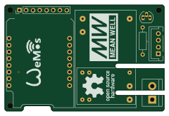 ESP8266
HASwitchPlate
aderusha
60 × 40 mm8 parts2LMIT738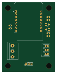 ESP8266
RatGDO-OpenSource-D1Mini-ESP8266
Kaldek
47.8 × 63.3 mm12 parts2LMIT506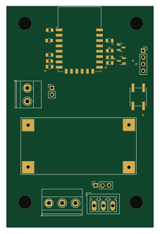 ESP8266
RatGDO-OpenSource-Bare-ESP8266
55 × 82.7 mm20 parts2LMIT506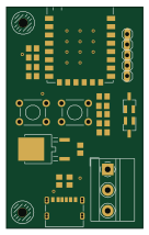 ESP8266
Goatgdo
32.9 × 53.3 mm23 parts2LMIT506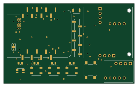 ESP8266
Iaq board
nkitanov
70.1 × 43.2 mm17 parts2LNo license398