
Vumeter schematics

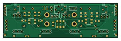
About the Vumeter schematics PCB
Vumeter schematics is an open source Microchip SAM PCB design by wyager, published on GitHub under the MIT license. It is a 2-layer board measuring 100 × 30 mm, with 47 components from 20 distinct parts.
Its main chip is the ATSAMD11C14, from the Microchip SAM family. Other key parts include the LM358, LM1117-3.3, NCH8200HV and TPS2281DBVR. By type, the board carries 7 ICs, 7 connectors, 4 transistors and 2 jumpers.
It belongs with the audio, displays & leds and usb & debug tools designs in this gallery.
From the project
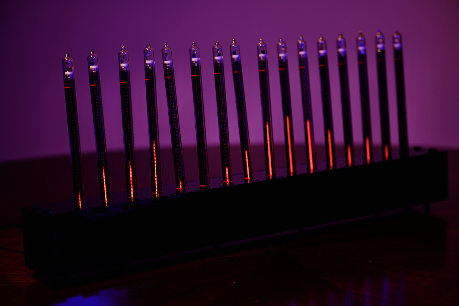
A nixie tube audio meter
Go into code/audioboard and code/tubeboard and run cargo build --release. (Without --release, the binaries may be too large.)
Plug your AVR-ICE or similar JTAG programmer into the tube board via the programming header and run ./program.sh.
Plug in your teensy over USB, put it in programming mode, and run ./program.sh
Get KiCad and open the schematics. How to export the schematics depends on your choice of PCB manufacturer. They should have instructions available online.
Main components on the Vumeter schematics
Vumeter schematics bill of materials (BOM)
47 components, 20 distinct parts.
| Qty | Part | Footprint | Refs |
|---|---|---|---|
| 2 | LM358 | SOIC-8_3.9x4.9mm_P1.27mm | U1, U4 |
| 1 | ATSAMD11C14 | SOIC-14_3.9x8.7mm_P1.27mm | U2 |
| 1 | LM1117-3.3 | SOT-223-3_TabPin2 | U3 |
| 2 | NCH8200HV | NCH8200HV | U5, U6 |
| 1 | TPS2281DBVR | SOT-23-6 | U7 |
| 4 | MJE340 | TO-126-3_Vertical-HV | Q1, Q2, Q3, Q4 |
| 1 | SWD | PinHeader_2x05_P1.27mm_Vertical-smallholes | J1 |
| 2 | Conn_01x04 | PinHeader_1x04_P2.54mm_Vertical | J2, J3 |
| 1 | Standoff_1 | PinSocket_1x04_P2.54mm_Vertical | J4 |
| 1 | Standoff_2 | PinSocket_1x04_P2.54mm_Vertical | J5 |
| 2 | Conn_01x01_Male | PinHeader_1x01_P2.54mm_Vertical | J6, J7 |
| 5 | 0.1u | C_1206_3216Metric | C_decouple1, C_pwm1, C_pwm2, C_pwm3, C_pwm4 |
| 2 | 10u | C_1206_3216Metric | C_pwr1, C_pwr2 |
| 1 | HV Bridge | R_1206_3216Metric | JP1 |
| 1 | HV_pwr | PinHeader_1x02_P2.54mm_Vertical | JP2 |
| 4 | IN-13 | fixed-IN-13-footprint-wide-sockets | N1, N2, N3, N4 |
| 4 | 550k | R_Axial_DIN0207_L6.3mm_D2.5mm_P10.16mm_Horizontal | R_Cathode1, R_Cathode2, R_Cathode3, R_Cathode4 |
| 4 | 330 | R_1206_3216Metric | R_Sense1, R_Sense2, R_Sense3, R_Sense4 |
| 4 | 3266X >1k | Potentiometer_Bourns_3266X_Horizontal | R_adj1, R_adj2, R_adj3, R_adj4 |
| 4 | 5k | R_1206_3216Metric | R_pwm1, R_pwm2, R_pwm3, R_pwm4 |
Vumeter schematics design files
The KiCad project lives in the wyager/vumeter repository on GitHub; these links point at the commit this page was built from.
Vumeter schematics: common questions
What microcontroller does the Vumeter schematics use?
The Vumeter schematics is built around the ATSAMD11C14, from the Microchip SAM family.
How big is the Vumeter schematics PCB?
The Vumeter schematics measures 100 × 30 mm, has 2 copper layers and is 1.6 mm thick.
How many components are on the Vumeter schematics?
47 components, from 20 distinct parts. The full bill of materials is listed on this page.
Where can I download the Vumeter schematics design files?
From the wyager/vumeter repository on GitHub, which has the KiCad layout and the schematic; the links under Design files point to each one.
Can I use the Vumeter schematics design in my own project?
Yes, under the terms of its MIT license, which wyager chose for the repository.
Can I test firmware for the Vumeter schematics without the hardware?
Yes. HardLabs builds a simulation of the board from its netlist and BOM, so you can run and debug Microchip SAM firmware against it before you order a PCB.
More boards in vumeter

Similar boards
 Microchip SAM
Microcontroller Expansion Card
FrameworkComputer
26 × 30 mm24 parts2LCC-BY-4.01.1k Microchip SAM
Taco Raven
VoronDesign
120 × 113 mm349 parts4LGPL-3.01.1k Microchip SAM
Fpgaboy
Wren6991
50 × 50 mm89 parts4LNo license508 Microchip SAM
OpenDropV4
GaudiLabs
124 × 115.4 mm118 parts2LGPL-3.0487 Microchip SAM
ModulAdapter universal
100 × 69.5 mm45 parts2LGPL-3.0487 Microchip SAM
Kira
kiibohd
366.9 × 114.3 mm400 partsCERN-OHL-1.2415