
Pulser V2 HV Board

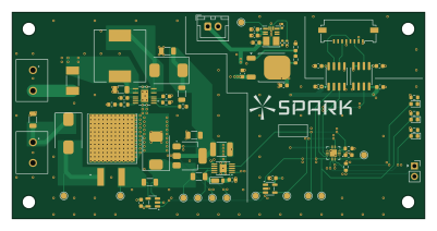
About the Pulser V2 HV Board
Pulser V2 HV Board is an open source AVR/Arduino PCB design by xy-kasumi, published on GitHub. It is a 4-layer board measuring 100 × 50 mm, with 62 components from 39 distinct parts.
Its main chip is the ATTINY1616-M, from the AVR/Arduino family. Other key parts include the ADUM1200AR, INA281A2, LTC7001, TLV3201 and LM317_DPAK. By type, the board carries 22 capacitors, 16 resistors, 9 ICs, 7 diodes, 5 connectors and 1 transistor.
From the project
WIP "Pulser" EDM board
Explicitly designed for plunge EDM. But probably will work for wire EDM too.
Created for https://github.com/xy-kasumi/Spark project.
10A max pulse (see module spec for details) Designed for reliablity and modular testability (especially stress testing)
Assembly PCB (pcb/ JLCPCB friendly KiCad files (all manufacturable using "Economical PCBA" process)) ctrl-r2 hv-r4 hc-r3 firmware (ATtiny1616), for ctrl and hv enclosure: 3D print data in assy * needs a few other parts (12V fans & heatsinks)
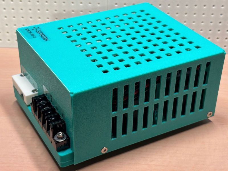
Main components on the Pulser V2 HV Board
Pulser V2 HV Board bill of materials (BOM)
62 components, 39 distinct parts — part numbers from the project's BOM.
| Qty | Part | Footprint | Refs |
|---|---|---|---|
| 2 | ADUM1200AR ADuM1200AR | SOIC-8_3.9x4.9mm_P1.27mm | U1, U7 |
| 1 | INA281A2 | SOT-23-5 | U2 |
| 1 | LTC7001 | MSOP-10-1EP_3x3mm_P0.5mm_EP1.68x1.88mm | U3 |
| 1 | TLV3201 | SOT-23-5 | U4 |
| 1 | LM317_DPAK | TO-252-2 | U5 |
| 1 | LT8365 | AD-MSOP-LT8365 | U6 |
| 1 | TPSM365R6 | TI-RDN0011A-MFG | U9 |
| 1 | ATTINY1616-M ATtiny1616-M | VQFN-20-1EP_3x3mm_P0.4mm_EP1.7x1.7mm | U11 |
| 1 | C537930 Q_NMOS_GDS | SOT-223-3_TabPin2 | Q1 |
| 2 | C8269 Screw_Terminal 2pin | Wurth_TerminalBlock_2pin_P5mm_691137710002 | J1, J2 |
| 1 | CONN_01X02_PIN Conn_01x02_Pin | JST_XH_B2B-XH-A_1x02_P2.50mm_Vertical | J3 |
| 1 | CONN_01X02_SOCKET Conn_01x02_Socket | PinSocket_1x02_P2.54mm_Vertical | J5 |
| 1 | CONN_01X08_PIN Conn_01x08_Pin | Molex_200528-0080_1x08-1MP_P1.00mm_Horizontal | J6 |
| 1 | C142852 2A | Fuse_Littelfuse-NANO2-451_453 | F1 |
| 3 | C241922 150V 2A | D_SMC | D1, D2, D5 |
| 3 | LED | LED_0603_1608Metric | D3, D4, D7 |
| 1 | C509964 150V 250mA | D_TUMD2 | D6 |
| 1 | 150UH 150uH | L_12x12mm_H8mm | L1 |
| 3 | C113894 100nF 200V | C_1206_3216Metric | C1, C3, C10 |
| 1 | C3037685 1uF 200V | C_1812_4532Metric | C2 |
Show 19 more
| Qty | Part | Footprint | Refs |
|---|---|---|---|
| 9 | 0.1U 0.1u | C_0603_1608Metric | C4, C5, C6, C7, C14, C15, C16, C17 +1 |
| 4 | 1u | C_0603_1608Metric | C8, C11, C29, C30 |
| 1 | C13585 10uF 50V | C_1206_3216Metric | C9 |
| 1 | 0.22U 0.22u | C_0603_1608Metric | C12 |
| 1 | 1n | C_0603_1608Metric | C13 |
| 1 | 1u | C_0402_1005Metric | C26 |
| 1 | 10U 10u | C_0603_1608Metric | C27 |
| 1 | C25334 100mΩ 120V | R_1206_3216Metric | R1 |
| 2 | 4.7K 4.7k | R_0603_1608Metric | R2, R7 |
| 1 | 100K 100k | R_1206_3216Metric | R3 |
| 1 | 100 | RESI-TO263 | R4 |
| 1 | 1k | R_0603_1608Metric | R6 |
| 1 | 110K 110k | R_0402_1005Metric | R9 |
| 1 | 10K 10k | R_0402_1005Metric | R10 |
| 1 | 270 | R_0603_1608Metric | R14 |
| 1 | 820 | R_0603_1608Metric | R15 |
| 1 | 430K 430k | R_1206_3216Metric | R16 |
| 4 | 100K 100k | R_0603_1608Metric | R17, R19, R20, R21 |
| 1 | 7.5K 7.5k | R_0603_1608Metric | R18 |
Pulser V2 HV Board design files
The KiCad project lives in the xy-kasumi/Spark-pulser repository on GitHub; these links point at the commit this page was built from.
Pulser V2 HV Board: common questions
What microcontroller does the Pulser V2 HV Board use?
The Pulser V2 HV Board is built around the ATTINY1616-M, from the AVR/Arduino family.
How big is the Pulser V2 HV Board?
The Pulser V2 HV Board measures 100 × 50 mm, has 4 copper layers and is 1.566 mm thick.
How many components are on the Pulser V2 HV Board?
62 components, from 39 distinct parts, with part numbers taken from the project's own BOM. The full bill of materials is listed on this page.
Where can I download the Pulser V2 HV Board design files?
From the xy-kasumi/Spark-pulser repository on GitHub, which has the KiCad layout, the schematic and the BOM; the links under Design files point to each one.
Can I use the Pulser V2 HV Board design in my own project?
The repository has no license, so all rights stay with xy-kasumi. Use it as a reference, and ask the author before reusing the design.
Can I test firmware for the Pulser V2 HV Board without the hardware?
Yes. HardLabs builds a simulation of the board from its netlist and BOM, so you can run and debug AVR/Arduino firmware against it before you order a PCB.
More boards in Spark-pulser
Similar boards
 AVR/Arduino
Magspoof
samyk
35 × 29 mm11 parts2LNo license4.2k AVR/Arduino
Redox keyboard
mattdibi
162.2 × 126.5 mm77 parts2LMIT2.0k AVR/Arduino
Labrador
espotek-org
36.8 × 34.7 mm75 parts2LNo license1.2k AVR/Arduino
ModuleV450
stuartpittaway
30 × 61.4 mm39 parts2LCC-BY-NC-4.01.1k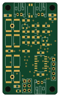 AVR/Arduino
V4
30 × 50 mm38 parts2LCC-BY-NC-4.01.1k AVR/Arduino
Discipline
coseyfannitutti
304.9 × 122.8 mm170 parts2LCC-BY-NC-4.01.0k