
Inercia floppy badge

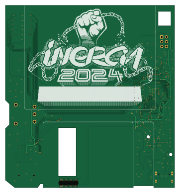
About the Inercia floppy badge PCB
Inercia floppy badge is an open source RP2040/RP2350 PCB design by afonsus1997, published on GitHub. It is a 2-layer board measuring 90 × 97 mm, with 76 components from 36 distinct parts.
Its main chip is the RP2040, from the RP2040/RP2350 family. Other key parts include the USBLC6-2P6, W25Q32JVSS, MAX98357AETE_T and TPS63802DLAR. By type, the board carries 29 resistors, 21 capacitors, 8 connectors, 6 switches, 5 ICs and 4 diodes.
It belongs with the wearables and power & battery designs in this gallery.
From the project
Missed last year’s Inércia 2023 badge? This year, they’re back and even better! Inércia 2024 badges now come with a mini OLED screen—perfect for displaying custom text, animations, and more, alongside the ability to play your favorite .mod tunes.
Missed last year’s Inércia 2023 badge? This year, they’re back and even better! Inércia 2024 badges now come with a mini OLED screen—perfect for displaying custom text, animations, and more, alongside the ability to play your favorite .mod tunes.
JLCPCB helped make this project possible! All the manufacturing and assembly of the prototypes and the final badges were made using JLCPCB services.
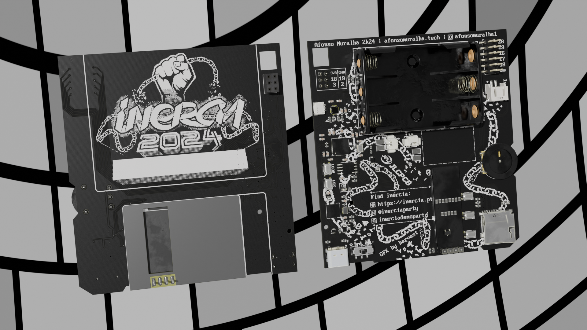
Main components on the Inercia floppy badge
Inercia floppy badge bill of materials (BOM)
76 components, 36 distinct parts — part numbers from the project's BOM.
| Qty | Part | Footprint | Refs |
|---|---|---|---|
| 1 | RP2040 | QFN-56-1EP_7x7mm_P0.4mm_EP3.2x3.2mm | U1 |
| 1 | USBLC6-2P6 | SOT-666 | U2 |
| 1 | W25Q32JVSS | SOIC-8_5.23x5.23mm_P1.27mm | U4 |
| 1 | MAX98357AETE_T | QFN50P300X300X80-17N | U5 |
| 1 | TPS63802DLAR | VREG_TPS63802DLAR | U6 |
| 1 | DMG3415U | SOT-23 | Q1 |
| 1 | 12MHZ | Crystal_SMD_3225-4Pin_3.2x2.5mm | Y1 |
| 1 | USB_C_RECEPTACLE_USB2.0 USB_C_Receptacle_USB2.0 | USB_C_Receptacle_HCTL_HC-TYPE-C-16P-01A | J1 |
| 1 | MICRO_SD_CARD_DET1 Micro_SD_Card_Det1 | J_sd_micro_socket | J2 |
| 1 | CONN_01X03_MOUNTINGPIN Conn_01x03_MountingPin | JST_SH_SM03B-SRSS-TB_1x03-1MP_P1.00mm_Horizontal | J3 |
| 2 | CONN_01X02_SHIELDED Conn_01x02_Shielded | CONN-SMD_2P-P1.25_HC_HCZZ0001-2 | J4, J101 |
| 1 | CONN_01X04 Conn_01x04 | OLED_SSD1306_128x32_0.91 | J6 |
| 1 | CONN_02X06_ODD_EVEN Conn_02x06_Odd_Even | PinHeader_2x06_P2.54mm_Vertical_SMD | J7 |
| 1 | CONN_01X02_SHIELDED Conn_01x02_Shielded | CONN-SMD_P2.00_S2B-PH-SM4-TB-LF-SN | J102 |
| 5 | SW_MEC_5E | SW_SKRPACE010 | SW2, SW3, SW4, SW5, SW6 |
| 1 | C500056 SW_Push_DPDT | SS-3235S-L2 | SW7 |
| 3 | C50553 D_Schottky | D_SOD-123F | D1, D101, D102 |
| 1 | LED | LED_0603_1608Metric | D2 |
| 1 | 0.47UH 0.47uH | L_Chilisin_BMRB00050512 | L101 |
| 12 | 100N 100n | C_0603_1608Metric | C3, C4, C6, C7, C8, C9, C10, C11 +4 |
Show 16 more
| Qty | Part | Footprint | Refs |
|---|---|---|---|
| 2 | 1u | C_0603_1608Metric | C5, C13 |
| 2 | 27P 27p | C_0603_1608Metric | C15, C16 |
| 2 | 10U 10u | C_0603_1608Metric | C18, C22 |
| 2 | 220P 220p | C_0603_1608Metric | C20, C21 |
| 1 | 22U 22u | C_0603_1608Metric | C23 |
| 1 | 511K 511k | R_0603_1608Metric | R1 |
| 3 | 91K 91k | R_0402_1005Metric | R2, R105, R108 |
| 3 | 0 | R_0603_1608Metric | R3, R24, R103 |
| 2 | 100 | R_0402_1005Metric | R4, R25 |
| 4 | 10K 10k | R_0603_1608Metric | R5, R109, R110, R111 |
| 2 | 5.1K 5.1k | R_0603_1608Metric | R6, R7 |
| 7 | 1k | R_0402_1005Metric | R9, R10, R13, R14, R17, R18, R20 |
| 2 | 27.4 | R_0402_1005Metric | R11, R12 |
| 2 | 4.7K 4.7k | R_0603_1608Metric | R15, R16 |
| 1 | 1M | R_0603_1608Metric | R21 |
| 2 | 62K 62k | R_0402_1005Metric | R106, R107 |
Inercia floppy badge design files
The KiCad project lives in the afonsus1997/Inercia-floppy-badge repository on GitHub; these links point at the commit this page was built from.
Inercia floppy badge: common questions
What microcontroller does the Inercia floppy badge use?
The Inercia floppy badge is built around the RP2040, from the RP2040/RP2350 family.
How big is the Inercia floppy badge PCB?
The Inercia floppy badge measures 90 × 97 mm, has 2 copper layers and is 1.6 mm thick.
How many components are on the Inercia floppy badge?
76 components, from 36 distinct parts, with part numbers taken from the project's own BOM. The full bill of materials is listed on this page.
Where can I download the Inercia floppy badge design files?
From the afonsus1997/Inercia-floppy-badge repository on GitHub, which has the KiCad layout, the schematic and the BOM; the links under Design files point to each one.
Can I use the Inercia floppy badge design in my own project?
The repository has no license, so all rights stay with afonsus1997. Use it as a reference, and ask the author before reusing the design.
Can I test firmware for the Inercia floppy badge without the hardware?
Yes. HardLabs builds a simulation of the board from its netlist and BOM, so you can run and debug RP2040/RP2350 firmware against it before you order a PCB.
Similar boards
 RP2040/RP2350
Open Book Abridged Edition
joeycastillo
85 × 115 mm29 parts2LCC-BY-SA-4.08.1k RP2040/RP2350
Corne
foostan
277.2 × 107.5 mm164 parts2LCC-BY-4.07.7k RP2040/RP2350
Corne
277.2 × 107.5 mm164 parts2LCC-BY-4.07.7k RP2040/RP2350
Jitx design
gusmanb
55.5 × 65 mm26 parts4LGPL-3.05.0k RP2040/RP2350
LogicAnalyzer
57 × 55.2 mm6 parts2LGPL-3.05.0k RP2040/RP2350
Main
google
98 × 71 mm102 parts2LApache-2.02.9k