
Sd mux

About the Sd mux PCB
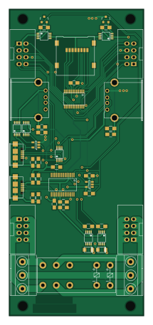
Sd mux is an open source PCB design by agners, published on GitHub under the Apache-2.0 license. It is a 2-layer board measuring 50 × 114 mm, with 48 components from 21 distinct parts.
Other key parts include the TS3USB30EDGSR, FT245RL, 74AHC1G14 and TS3A27518E. By type, the board carries 11 connectors, 11 resistors, 9 capacitors, 8 transistors, 5 ICs and 2 diodes.
It belongs with the usb & debug tools designs in this gallery.
From the project
Fork of sd-mux from https://git.tizen.org/cgit/tools/testlab/sd-mux/ with SDReWire support
Fork of sd-mux-ctrl from the Tizen git repository. This version supports SDReWire as well as SDWire. To use this version make sure to set the product string.
Use the "set-serial" command to write serial as well as product string:
With that you should be able to switch between DUT (device under test) and TS (test system) mode:
Note: Since sd-mux-ctrl needs full device access using sd-mux-ctrl does not allow you to use the USB to UART tty at the same time. This fork is meant as a stop-gap/migration solution.
Main components on the Sd mux
Sd mux bill of materials (BOM)
48 components, 21 distinct parts.
| Qty | Part | Footprint | Refs |
|---|---|---|---|
| 1 | TS3USB30EDGSR | msoic-10 | U1 |
| 1 | FT245RL | ssop-28 | U2 |
| 2 | 74AHC1G14 | SOT-23-5 | U3, U5 |
| 1 | TS3A27518E | tssop-24 | U4 |
| 6 | IRF7606PBF | msoic-8 | Q1, Q2, Q3, Q4, Q7, Q8 |
| 2 | 2N7002 | SOT-23 | Q5, Q6 |
| 1 | USDCARD | microsd_socket | J1 |
| 1 | USB_OTG | conn_usb_B_micro | P1 |
| 1 | 629105136821 | conn_usb_B_micro | P2 |
| 2 | 61400416021 | conn_usb_A | P3, P4 |
| 2 | IDC_02X04 | PSB_IDC_4x2 | P5, P6 |
| 2 | MKDS 1,5/3 | cons_1,5x3 | P7, P10 |
| 2 | CONN_02X02 | PSB_IDC__4x2 | P8, P9 |
| 1 | G2RK-2 | G2RK-2 | RL1 |
| 2 | ES1AL | do219ab | D1, D2 |
| 1 | MI0805K400R-10 | R_0805_HandSoldering | FB1 |
| 4 | 27p | C_0805_HandSoldering | C1, C2, C4, C5 |
| 4 | 100n | C_0805_HandSoldering | C3, C6, C7, C8 |
| 1 | 4.7u | C_0805_HandSoldering | C9 |
| 4 | 4.7K | R_0805_HandSoldering | R1, R2, R3, R4 |
Show 1 more
| Qty | Part | Footprint | Refs |
|---|---|---|---|
| 7 | 10K | R_0805_HandSoldering | R5, R6, R7, R8, R9, R10, R11 |
Sd mux design files
The KiCad project lives in the agners/sd-mux repository on GitHub; these links point at the commit this page was built from.
Sd mux: common questions
How big is the Sd mux PCB?
The Sd mux measures 50 × 114 mm, has 2 copper layers and is 1.6 mm thick.
How many components are on the Sd mux?
48 components, from 21 distinct parts. The full bill of materials is listed on this page.
Where can I download the Sd mux design files?
From the agners/sd-mux repository on GitHub, which has the KiCad layout; the links under Design files point to each one.
Can I use the Sd mux design in my own project?
Yes, under the terms of its Apache-2.0 license, which agners chose for the repository.
More boards in sd-mux
Similar boards
USB Hub Test
osy
50 × 50 mm85 parts4LCC-BY-4.0703
XG Station Power
54.3 × 91 mm9 parts2LCC-BY-4.0703
FW-EC-DongleHiderPlus
LeoDJ
28.2 × 26.1 mm14 parts4LCERN-OHL-W-2.0497
Adapter tsop48
bbogush
48 × 33 mm3 parts2LGPL-3.0389
Adapter tsop48 solder
48 × 33 mm3 parts2LGPL-3.0389
Adapter soic8 solder
48 × 20 mm3 parts2LGPL-3.0389