
MPXDecorder-V2

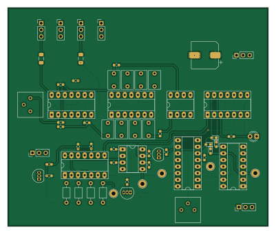
About the MPXDecorder-V2 PCB
MPXDecorder-V2 is an open source PCB design by akira345, published on GitHub. It is a 2-layer board measuring 100 × 84.2 mm, with 119 components from 42 distinct parts.
Other key parts include the CD4066BE, 4046, UPC458, 74HC74 and LM393. By type, the board carries 53 resistors, 35 capacitors, 8 ICs, 7 connectors, 6 diodes and 5 test points.
It belongs with the rf & radio designs in this gallery, and the repository also holds 1 earlier revision of it.
From the project
専用ICを使用せずFMステレオ受信機を自作するプロジェクト
生成AIを用いて、専用ICを使用せず日本のワイドFM受信機を設計、自作するプロジェクトです。 可能な限り汎用品を用いて自作し、専用ICの内部構造や動作原理を学習することを目的に作成されました。
また、各種生成AIを使用し、現時点でどこまでアナログ回路の設計、および評価が可能か?を研究する目的でもあります。
FM フロントエンド RF増幅段 局部発振 ミキサー IF リミッターアンプ + クワドラチャ検波 差動対4段 汎用トランジスタと手巻きコイルによるクワドラチャ検波 FM MPX 復調 * 汎用PLL IC + OpAMP + アナログスイッチによるFMステレオの復調
Main components on the MPXDecorder-V2
MPXDecorder-V2 bill of materials (BOM)
119 components, 42 distinct parts — part numbers from the project's BOM.
| Qty | Part | Footprint | Refs |
|---|---|---|---|
| 1 | CD4066BE | DIP-14_W7.62mm_Socket_LongPads | U1 |
| 1 | 4046 | DIP-16_W7.62mm_Socket_LongPads | U2 |
| 3 | UPC458 upc458 | DIP-14_W7.62mm_Socket_LongPads | U3, U6, U7 |
| 1 | 74HC74 | DIP-14_W7.62mm_Socket_LongPads | U4 |
| 1 | LM393 | DIP-8_W7.62mm_Socket_LongPads | U5 |
| 1 | NJM4558 | DIP-8_W7.62mm_Socket_LongPads | U8 |
| 3 | 2SC1815 | TO-92_Inline | Q1, Q2, Q3 |
| 1 | MPX-IN | PinHeader_1x03_P2.54mm_Vertical | J1 |
| 1 | OUT-L | PinHeader_1x03_P2.54mm_Vertical | J2 |
| 3 | GND | PinHeader_1x03_P2.54mm_Vertical | J3, J5, J7 |
| 1 | OUT-R | PinHeader_1x03_P2.54mm_Vertical | J4 |
| 1 | 5V | PinHeader_1x03_P2.54mm_Vertical | J6 |
| 1 | 10K 10k | Potentiometer_Bourns_3386P_Vertical | RV1 |
| 1 | 5k | Potentiometer_Bourns_3386P_Vertical | RV2 |
| 1 | 19KHZ-SIN 19KHz-Sin | TestPoint_Loop_D2.54mm_Drill1.5mm_Beaded | TP1 |
| 1 | 19KHZ-RECT 19KHz-Rect | TestPoint_Loop_D2.54mm_Drill1.5mm_Beaded | TP3 |
| 1 | 38KHZ-PLL 38KHz-PLL | TestPoint_Loop_D2.54mm_Drill1.5mm_Beaded | TP5 |
| 1 | PILOT-V | TestPoint_Loop_D2.54mm_Drill1.5mm_Beaded | TP6 |
| 1 | VCO | TestPoint_Loop_D2.54mm_Drill1.5mm_Beaded | TP7 |
| 5 | 1S1588 1s1588 | D_0603_1608Metric_Pad1.05x0.95mm_HandSolder | D1, D3, D4, D5, D6 |
Show 22 more
| Qty | Part | Footprint | Refs |
|---|---|---|---|
| 1 | STEREO-LED | LED_D3.0mm | D2 |
| 4 | 1u | C_0603_1608Metric_Pad1.08x0.95mm_HandSolder | C1, C5, C12, C36 |
| 13 | 0.1U 0.1u | C_0603_1608Metric_Pad1.08x0.95mm_HandSolder | C2, C6, C7, C8, C9, C13, C16, C19 +5 |
| 3 | 1n | C_0603_1608Metric_Pad1.08x0.95mm_HandSolder | C3, C17, C18 |
| 4 | 0.01U 0.01u | C_Axial_L3.8mm_D2.6mm_P7.50mm_Horizontal | C10, C11, C14, C15 |
| 8 | 2.2N 2.2n | C_Rect_L7.0mm_W4.5mm_P5.00mm | C23, C24, C25, C26, C29, C30, C31, C32 |
| 1 | 330u 25v | CP_Elec_10x10 | C28 |
| 2 | 10U 10u | C_1206_3216Metric_Pad1.33x1.80mm_HandSolder | C33, C34 |
| 1 | 43K 43k | R_0603_1608Metric_Pad0.98x0.95mm_HandSolder | R1 |
| 2 | 470K 470k | R_0603_1608Metric_Pad0.98x0.95mm_HandSolder | R2, R3 |
| 17 | 10K 10k | R_0603_1608Metric_Pad0.98x0.95mm_HandSolder | R4, R7, R9, R24, R26, R27, R32, R33 +9 |
| 10 | 4.7K 4.7k | R_0603_1608Metric_Pad0.98x0.95mm_HandSolder | R5, R10, R43, R44, R47, R48, R53, R54 +2 |
| 3 | 47 | R_0603_1608Metric_Pad0.98x0.95mm_HandSolder | R6, R16, R23 |
| 1 | 20K 20k | R_0603_1608Metric_Pad0.98x0.95mm_HandSolder | R8 |
| 9 | 100K 100k | R_0603_1608Metric_Pad0.98x0.95mm_HandSolder | R11, R12, R20, R21, R30, R31, R34, R50 +1 |
| 2 | 1k | R_0603_1608Metric_Pad0.98x0.95mm_HandSolder | R13, R28 |
| 1 | 680K 680k | R_0603_1608Metric_Pad0.98x0.95mm_HandSolder | R14 |
| 2 | 7.5K 7.5k | R_0603_1608Metric_Pad0.98x0.95mm_HandSolder | R15, R22 |
| 1 | 5.1K 5.1k | R_0603_1608Metric_Pad0.98x0.95mm_HandSolder | R17 |
| 1 | 1.5K 1.5k | R_0603_1608Metric_Pad0.98x0.95mm_HandSolder | R18 |
| 2 | 15K 15k | R_0603_1608Metric_Pad0.98x0.95mm_HandSolder | R19, R25 |
| 1 | 1OK 1ok | R_0603_1608Metric_Pad0.98x0.95mm_HandSolder | R42 |
MPXDecorder-V2 design files
The KiCad project lives in the akira345/Discrete-FM-Radio-Receiver-Project repository on GitHub; these links point at the commit this page was built from.
MPXDecorder-V2: common questions
How big is the MPXDecorder-V2 PCB?
The MPXDecorder-V2 measures 100 × 84.2 mm, has 2 copper layers and is 1.6 mm thick.
How many components are on the MPXDecorder-V2?
119 components, from 42 distinct parts, with part numbers taken from the project's own BOM. The full bill of materials is listed on this page.
Where can I download the MPXDecorder-V2 design files?
From the akira345/Discrete-FM-Radio-Receiver-Project repository on GitHub, which has the KiCad layout, the schematic and the BOM; the links under Design files point to each one.
Can I use the MPXDecorder-V2 design in my own project?
The repository has no license, so all rights stay with akira345. Use it as a reference, and ask the author before reusing the design.
More boards in Discrete-FM-Radio-Receiver-Project
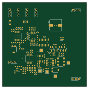
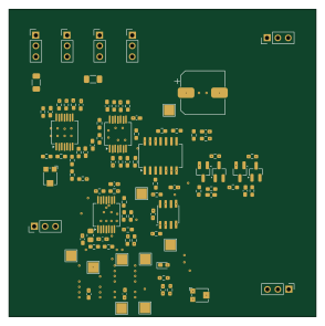
Earlier revisions in the repo: MPXDecorder
Similar boards
Hat
pa3gsb
65 × 56 mm81 parts2LNo license675
Radioberry juice
65 × 56 mm87 parts2LNo license675
Radioberry preamp
65 × 56 mm137 parts2LNo license675
Goodwatch20
travisgoodspeed
25.6 × 27.6 mm20 parts2LNo license568
GoodPocketWatch
75.2 × 101.2 mm56 parts2LNo license568
Goodwatch31
25.6 × 27.6 mm23 parts2LNo license568