
Piridium bus

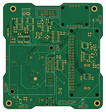
About the Piridium bus PCB
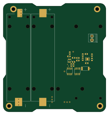
Piridium bus is an open source Raspberry Pi PCB design by Alan-JH, published on GitHub under the CC-BY-NC-4.0 license. It is a 4-layer board measuring 90.2 × 95.9 mm, with 156 components from 58 distinct parts.
Its main chip is the Raspberry_Pi_Zero, from the Raspberry Pi family. Other key parts include the LM1117-3.3, MAX6369, TPS54394RSAR, INA180A3 and 74HC126. By type, the board carries 51 resistors, 37 capacitors, 17 ICs, 14 transistors, 11 diodes and 9 connectors.
It belongs with the power & battery, science & space and rf & radio designs in this gallery.
From the project
Flight Computer Board for TJ Cubesat Bus design
Clock: DS3232M RTC with CR2032 Battery Backup
Battery: Six 18650 Li-Ion cells (builder's discretion, recommend protected 3-4Ah) in a 3P2S configuration
Battery protection: ~7.7A overcurrent protection (charge & discharge), 4.29V/cell overcharge protection with hysteresis down to 4.05V/cell, 3V/cell overdischarge protection with hysteresis up to 3.2V/cell
Solar input: 4 input connectors feeding two regulators with 25V Max (limited by the voltage divider for telemetry) with charge cutoff at 8.27V, MPPT settable using a trim pot
Main components on the Piridium bus
Piridium bus bill of materials (BOM)
156 components, 58 distinct parts.
| Qty | Part | Footprint | Refs |
|---|---|---|---|
| 1 | LM1117-3.3 | SOT-223-3_TabPin2 | U1 |
| 1 | MAX6369 | SOT-23-8 | U2 |
| 1 | TPS54394RSAR | Texas_S-PVQFN-N16_EP2.7x2.7mm_ThermalVias | U3 |
| 4 | INA180A3 | SOT-23-5 | U4, U9, U11, U13 |
| 1 | 74HC126 | SOIC-14_3.9x8.7mm_P1.27mm | U5 |
| 1 | DS3232M | SOIC-8_3.9x4.9mm_P1.27mm | U6 |
| 1 | MAX6035xxUR30 | SOT-23 | U7 |
| 1 | MCP3208 | SOIC-16_3.9x9.9mm_P1.27mm | U8 |
| 2 | LT3652EMSE | MSOP-12-1EP_3x4mm_P0.65mm_EP1.65x2.85mm | U10, U12 |
| 2 | SN74LVC1G14DBV | SOT-23-5 | U14, U16 |
| 2 | MAX4373F | SO-8_3.9x4.9mm_P1.27mm | U15, U17 |
| 1 | Raspberry_Pi_Zero | Raspberry Pi Zero | A1 |
| 1 | BNO055 | BNO055 | A2 |
| 1 | 9602N | 9602 | A3 |
| 7 | DMP3015LSSQ | SOIC-8_3.9x4.9mm_P1.27mm | Q1, Q3, Q5, Q6, Q8, Q10, Q13 |
| 2 | Si4186DY | SOIC-8_3.9x4.9mm_P1.27mm | Q2, Q4 |
| 5 | 2N7002 | SOT-23 | Q7, Q9, Q11, Q12, Q14 |
| 1 | EPS | TerminalBlock_Phoenix_PT-1,5-2-3.5-H_1x02_P3.50mm_Horizontal | J1 |
| 1 | INHIBITS | PinHeader_1x08_P2.54mm_Horizontal | J2 |
| 1 | MODEM UART | PinHeader_1x06_P2.54mm_Vertical | J3 |
Show 38 more
| Qty | Part | Footprint | Refs |
|---|---|---|---|
| 1 | ANT | SMA_Amphenol_901-144_Vertical | J4 |
| 1 | PAYLOAD | IDC-Header_2x05_P2.54mm_Vertical | J5 |
| 2 | IN1 | PinHeader_1x03_P2.54mm_Vertical | J6, J8 |
| 2 | IN2 | PinHeader_1x03_P2.54mm_Vertical | J7, J9 |
| 1 | CR2032 | CR2032-LINX-HLD-001-THM | BT1 |
| 1 | WDT_EN | PinHeader_1x02_P2.54mm_Vertical | JP1 |
| 2 | 100K | Bourns PVG3A | RV1, RV2 |
| 1 | 5V | TestPoint_Loop_D2.50mm_Drill1.0mm | TP1 |
| 2 | GND | TestPoint_Loop_D2.50mm_Drill1.0mm | TP2, TP3 |
| 1 | 5VP | TestPoint_Loop_D2.50mm_Drill1.0mm | TP4 |
| 2 | VIN | TestPoint_2Pads_Pitch2.54mm_Drill0.8mm | TP5, TP7 |
| 1 | LED | LED_0805_2012Metric | D1 |
| 4 | DFLS130L-7 | D_SOD-123 | D2, D3, D6, D7 |
| 2 | CMSH3-40MA | D_SMA | D4, D8 |
| 4 | RB051MM-2Y | D_SOD-123F | D5, D9, D10, D11 |
| 2 | 4.7uH | L_Abracon_ASPI-0630LR | L1, L2 |
| 2 | 10uH | L_AVX_LMLP07A7 | L3, L4 |
| 10 | 10uF | C_0805_2012Metric | C1, C7, C11, C21, C23, C25, C28, C30 +2 |
| 16 | 0.1uF | C_0805_2012Metric | C2, C3, C4, C14, C16, C17, C19, C20 +8 |
| 4 | 22uF | C_1210_3225Metric | C5, C6, C12, C13 |
| 2 | 0.1uF | C_0603_1608Metric | C8, C9 |
| 5 | 1uF | C_0805_2012Metric | C10, C15, C18, C24, C29 |
| 7 | 100K | R_0805_2012Metric | R1, R2, R9, R10, R12, R14, R21 |
| 5 | 100R | R_0805_2012Metric | R3, R6, R11, R13, R22 |
| 2 | 124K | R_0805_2012Metric | R4, R15 |
| 2 | 22.1K | R_0805_2012Metric | R5, R16 |
| 2 | 6K | R_0805_2012Metric | R7, R18 |
| 2 | 4K | R_0805_2012Metric | R8, R19 |
| 4 | 4m | R_1206_3216Metric | R17, R25, R34, R41 |
| 1 | 200K | R_0805_2012Metric | R20 |
| 12 | 10K | R_0805_2012Metric | R23, R24, R26, R27, R29, R36, R42, R43 +4 |
| 2 | 75K | R_0805_2012Metric | R28, R35 |
| 2 | 191K | R_0805_2012Metric | R30, R37 |
| 2 | 147K | R_0805_2012Metric | R31, R38 |
| 2 | 97.6K | R_0805_2012Metric | R32, R39 |
| 2 | 50m | R_1206_3216Metric | R33, R40 |
| 2 | 510K | R_0805_2012Metric | R44, R49 |
| 2 | 10m | R_1206_3216Metric | R46, R51 |
Piridium bus design files
The KiCad project lives in the Alan-JH/piridium-bus repository on GitHub; these links point at the commit this page was built from.
Piridium bus: common questions
What microcontroller does the Piridium bus use?
The Piridium bus is built around the Raspberry_Pi_Zero, from the Raspberry Pi family.
How big is the Piridium bus PCB?
The Piridium bus measures 90.2 × 95.9 mm, has 4 copper layers and is 1.56 mm thick.
How many components are on the Piridium bus?
156 components, from 58 distinct parts. The full bill of materials is listed on this page.
Where can I download the Piridium bus design files?
From the Alan-JH/piridium-bus repository on GitHub, which has the KiCad layout and the schematic; the links under Design files point to each one.
Can I use the Piridium bus design in my own project?
It is published under CC-BY-NC-4.0, which limits how it may be reused; read the license before building on it.
Can I test firmware for the Piridium bus without the hardware?
Yes. HardLabs builds a simulation of the board from its netlist and BOM, so you can run and debug Raspberry Pi firmware against it before you order a PCB.
More boards in piridium-bus
Similar boards
 Raspberry Pi
Open source rover
nasa-jpl
220 × 178 mm144 parts2LApache-2.09.7k Raspberry Pi
SPIRIT
SPIRIT-org
82 × 155 mm130 parts6LCERN-OHL-S-2.01.3k Raspberry Pi
CM5RevEng
schlae
55 × 40 mm417 parts10LNo license1.0k Raspberry Pi
Haxo hw
cardonabits
102.4 × 211.3 mm38 parts2LCustom license672 Raspberry Pi
PowerBook
BlueSCSI
74.5 × 56.3 mm78 parts2LGPL-3.0449 Raspberry Pi
Desktop 50 Pin TopConn
89.2 × 82.6 mm103 parts2LGPL-3.0449