
65uino

About the 65uino PCB
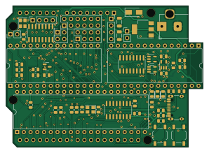
65uino is an open source PCB design by AndersBNielsen, published on GitHub under the Custom license license. It is a 2-layer board measuring 74.4 × 53.6 mm, with 80 components from 47 distinct parts.
Other key parts include the R6507, 74HC161, 6532, w27C512 and MIC5504-3.3YM5. By type, the board carries 19 resistors, 17 jumpers, 17 capacitors, 10 ICs, 8 connectors and 4 diodes.
It belongs with the retro computing and usb & debug tools designs in this gallery.
From the project
6502 learning platform in a familiar form factor
It's a green 6502 based learning platform in a familiar form factor and a contestant in the 2023 Hackaday Prize. By taking IC's out of the waste stream and into useful products we encourage recycling and reuse. It's a fun way to learn assembly programming and a tool you can use in your workshop for a lot more than you expect.
You can either make your own, get a PCB using the guide below or order a kit with SMD components presoldered from iMania.dk (IC's available if needed).
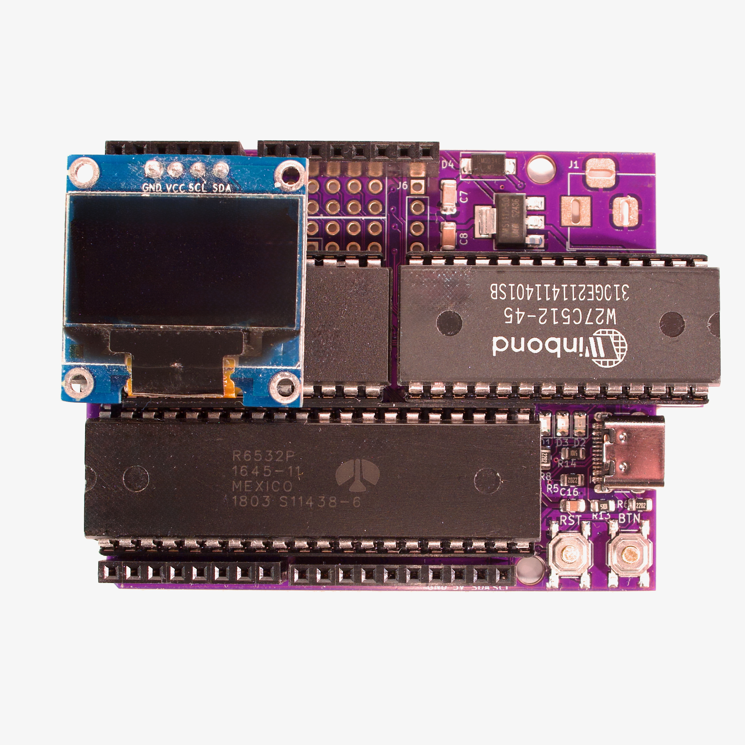
Main components on the 65uino
65uino bill of materials (BOM)
80 components, 47 distinct parts — part numbers from the project's BOM.
| Qty | Part | Footprint | Refs |
|---|---|---|---|
| 1 | R6507 | DIP-28_W15.24mm | U1 |
| 1 | 74HC161 | SOP-16_3.9x9.9mm_P1.27mm | U2 |
| 1 | 6532 | DIP-40_W15.24mm | U3 |
| 1 | w27C512 | DIP-28_W15.24mm | U4 |
| 1 | MIC5504-3.3YM5 | SOT-23-5 | U5 |
| 1 | AMS1117-5.0 | SOT-223-3_TabPin2 | U6 |
| 1 | SN74LVC1G14DBVR | SOT-23-5 | U7 |
| 1 | CH340G | SOIC-16_3.9x9.9mm_P1.27mm | U8 |
| 1 | 74HC138 | SOP-16_3.9x9.9mm_P1.27mm | U9 |
| 1 | 24C64S | SOT-23-5 | U10 |
| 1 | MMBT3906 | SOT-23 | Q1 |
| 1 | 1MHZ 8MHz | Crystal_SMD_3225-4Pin_3.2x2.5mm | X1 |
| 1 | 12MHz | Crystal_SMD_3225-4Pin_3.2x2.5mm | Y2 |
| 1 | Barrel | BarrelJack_Horizontal | J1 |
| 1 | C132563 GPCO | PinHeader_1x02_P2.54mm_Vertical | J2 |
| 1 | OLED | PinSocket_1x04_P2.54mm_Vertical | J3 |
| 1 | USB2.0_16P | USB_C_Receptacle_HCTL_HC-TYPE-C-16P-01A | J4 |
| 1 | Databus | PinHeader_2x04_P2.54mm_Vertical | J5 |
| 1 | Chip select | PinSocket_1x04_P2.54mm_Vertical | J6 |
| 1 | Addressbus | PinHeader_2x06_P2.54mm_Vertical | J7 |
Show 27 more
| Qty | Part | Footprint | Refs |
|---|---|---|---|
| 1 | Signals | PinHeader_2x02_P2.54mm_Vertical | J8 |
| 1 | SOLDERJUMPER_2_OPEN SolderJumper_2_Open | SolderJumper-2_P1.3mm_Open_RoundedPad1.0x1.5mm | JP1 |
| 3 | SOLDERJUMPER_2_BRIDGED SolderJumper_2_Bridged | SolderJumper-2_P1.3mm_Bridged_RoundedPad1.0x1.5mm | JP2, JP7, JP8 |
| 5 | SOLDERJUMPER_2_BRIDGED SolderJumper_2_Bridged | SolderJumper-2_P1.3mm_Open_RoundedPad1.0x1.5mm | JP3, JP4, JP5, JP6, JP9 |
| 1 | SOLDERJUMPER_2_BRIDGED Jumper | PinHeader_1x02_P2.54mm_Vertical | JP10 |
| 4 | SolderJumper_2_Bridged | SolderJumper-2_P1.3mm_Open_RoundedPad1.0x1.5mm | JP11, JP12, JP13, JP14 |
| 3 | SolderJumper_2_Bridged | SolderJumper-2_P1.3mm_Bridged_RoundedPad1.0x1.5mm | JP15, JP16, JP17 |
| 1 | C318884 RST | SW_SPST_TL3342 | SW1 |
| 1 | C318884 BTN | SW_SPST_TL3342 | SW2 |
| 1 | C2297 GREEN LED | LED_0805_2012Metric | D1 |
| 1 | C84256 RED LED | LED_0805_2012Metric | D2 |
| 1 | C34499 RED LED | LED_0805_2012Metric | D3 |
| 1 | 1N4007 | D_SMA | D4 |
| 2 | 100nF | C_0805_2012Metric | C1, C2 |
| 6 | 100NF 100nF | C_0805_2012Metric | C3, C4, C9, C11, C12, C13 |
| 2 | 1UF 1uF | C_0805_2012Metric | C5, C6 |
| 2 | 10UF 10uF | C_1206_3216Metric | C7, C8 |
| 2 | NC | C_0805_2012Metric | C10, C14 |
| 2 | 22p | C_0805_2012Metric | C15, C17 |
| 1 | 1uF | C_0805_2012Metric | C16 |
| 2 | 3k | R_0805_2012Metric | R1, R2 |
| 5 | NC | R_0805_2012Metric | R3, R4, R11, R12, R15 |
| 3 | 22K 22k | R_0805_2012Metric | R5, R6, R8 |
| 1 | 15K 22k | R_0805_2012Metric | R7 |
| 3 | 1k | R_0805_2012Metric | R9, R10, R19 |
| 4 | 5k1 | R_0805_2012Metric | R13, R14, R16, R17 |
| 1 | 22k | R_0805_2012Metric | R18 |
65uino design files
The KiCad project lives in the AndersBNielsen/65uino repository on GitHub; these links point at the commit this page was built from.
65uino: common questions
How big is the 65uino PCB?
The 65uino measures 74.4 × 53.6 mm, has 2 copper layers and is 1.6 mm thick.
How many components are on the 65uino?
80 components, from 47 distinct parts, with part numbers taken from the project's own BOM. The full bill of materials is listed on this page.
Where can I download the 65uino design files?
From the AndersBNielsen/65uino repository on GitHub, which has the KiCad layout, the schematic and the BOM; the links under Design files point to each one.
Can I use the 65uino design in my own project?
It is published under Custom license, which limits how it may be reused; read the license before building on it.
Similar boards
OpenTendo
Redherring32
196.3 × 118.7 mm93 parts2LTAPR-OHL-1.0850
Sram dev board
Wren6991
50 × 50 mm12 parts2LNo license508
24pin flex interposer
29 × 32 mm3 parts2LNo license508
FW-EC-DongleHiderPlus
LeoDJ
28.2 × 26.1 mm14 parts4LCERN-OHL-W-2.0490
GB-BRK-SLOT-A
Gekkio
81 × 80 mm20 parts2LCC-BY-4.0376
GB-BRK-SLOT-B
81 × 80 mm20 parts2LCC-BY-4.0376