
Channel ADC Interface RevC

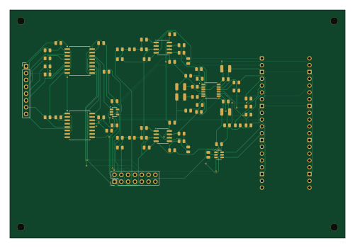
About the Channel ADC Interface RevC PCB
Channel ADC Interface RevC is an open source RP2040/RP2350 PCB design by AnishLanka, published on GitHub. It is a 2-layer board measuring 125 × 85 mm, with 69 components from 23 distinct parts.
Its main chip is the SC0915, from the RP2040/RP2350 family. Other key parts include the OPA2320AID, ADS8353IPW, ISO7741FDWR, ISO7721FDWR and SN74LVC1G08DBVR. By type, the board carries 35 resistors, 24 capacitors, 8 ICs and 2 connectors.
It belongs with the power & battery and test & measurement designs in this gallery.
From the project
By Pythagoras Carayannopoulos, Peter Zhao and Anish Lanka. Presentation: docs/PrototypeDemo2.pdf
By Pythagoras Carayannopoulos, Peter Zhao and Anish Lanka. Presentation: docs/PrototypeDemo2.pdf
Start with docs/RevCRelease/READMEFIRST.txt and docs/RevCRelease/IntegrationGuide.html`. Upload each board's manufacturing ZIP to JLCPCB as a separate bare PCB design. Do not upload the complete release archive as one PCB.
The signal generator sets the shape of the stimulation current. The power path provides the energy and voltage to push it. The two paths meet at the Howland, which turns the voltage command into a current.
Main components on the Channel ADC Interface RevC
Channel ADC Interface RevC bill of materials (BOM)
69 components, 23 distinct parts — part numbers from the project's BOM.
| Qty | Part | Footprint | Refs |
|---|---|---|---|
| 2 | OPA2320AID OPA2320 | SOIC-8_3.9x4.9mm_P1.27mm | U201, U202 |
| 1 | ADS8353IPW ADS8353 | TSSOP-16_4.4x5mm_P0.65mm | U204 |
| 1 | ISO7741FDWR ISO7741F | SOIC-16W_7.5x10.3mm_P1.27mm | U205 |
| 1 | ISO7721FDWR ISO7721F | SOIC-16W_7.5x10.3mm_P1.27mm | U206 |
| 1 | SC0915 Raspberry Pi Pico RP2040 | RaspberryPi_Pico_Common_THT | U207 |
| 1 | SN74LVC1G08DBVR SN74LVC1G08 | SOT-23-5 | U208 |
| 1 | SN74LVC2G17DBVR SN74LVC2G17 | SOT-23-6 | U209 |
| 1 | TSW-108-07-G-S HOST_CONTROL_TELEMETRY | PinHeader_1x08_P2.54mm_Vertical | J201 |
| 1 | TSW-107-07-G-D CORE_ADC_CONTROL_LINK | PinHeader_2x07_P2.54mm_Vertical | J202 |
| 2 | C0805C122F5GACTU 1.2n | C_0805_2012Metric | C201, C207 |
| 4 | C0805C102F5GACTU 1n | C_0805_2012Metric | C202, C204, C208, C210 |
| 2 | C0805C682F5GACTU 6.8n | C_0805_2012Metric | C203, C209 |
| 2 | C0805C822F5GACTU 8.2n | C_0805_2012Metric | C205, C211 |
| 10 | C0805C104K4RACTU 100n | C_0805_2012Metric | C206, C212, C219, C221, C223, C224, C225, C226 +2 |
| 4 | GRM32ER71C226KEA8L 22u | C_1210_3225Metric | C213, C216, C220, C222 |
| 4 | TNPW08052K00BEEA 2k | R_0805_2012Metric | R201, R202, R209, R210 |
| 2 | TNPW0805470RBEEA 470R | R_0805_2012Metric | R203, R211 |
| 2 | TNPW08051K47BEEA 1.47k | R_0805_2012Metric | R204, R212 |
| 4 | TNPW0805604RBEEA 604R | R_0805_2012Metric | R205, R206, R213, R214 |
| 4 | TNPW080510R0BEEA 10R | R_0805_2012Metric | R207, R208, R215, R216 |
Show 3 more
| Qty | Part | Footprint | Refs |
|---|---|---|---|
| 12 | TNPW080510K0BEEA 10k | R_0805_2012Metric | R221, R222, R223, R229, R230, R231, R232, R233 +4 |
| 5 | TNPW080533R0BEEA 33R | R_0805_2012Metric | R224, R225, R226, R227, R228 |
| 2 | WSL0805R1000FEA 0.1R | R_0805_2012Metric | R238, R239 |
Channel ADC Interface RevC design files
The KiCad project lives in the AnishLanka/BrainStimulation repository on GitHub; these links point at the commit this page was built from.
Channel ADC Interface RevC: common questions
What microcontroller does the Channel ADC Interface RevC use?
The Channel ADC Interface RevC is built around the SC0915, from the RP2040/RP2350 family.
How big is the Channel ADC Interface RevC PCB?
The Channel ADC Interface RevC measures 125 × 85 mm, has 2 copper layers and is 0.41116 mm thick.
How many components are on the Channel ADC Interface RevC?
69 components, from 23 distinct parts, with part numbers taken from the project's own BOM. The full bill of materials is listed on this page.
Where can I download the Channel ADC Interface RevC design files?
From the AnishLanka/BrainStimulation repository on GitHub, which has the KiCad layout, the schematic and the BOM; the links under Design files point to each one.
Can I use the Channel ADC Interface RevC design in my own project?
The repository has no license, so all rights stay with AnishLanka. Use it as a reference, and ask the author before reusing the design.
Can I test firmware for the Channel ADC Interface RevC without the hardware?
Yes. HardLabs builds a simulation of the board from its netlist and BOM, so you can run and debug RP2040/RP2350 firmware against it before you order a PCB.
More boards in BrainStimulation
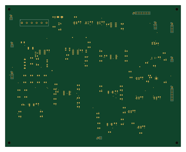
Channel Monitor C1
180 × 145 mm137 parts2LNo license1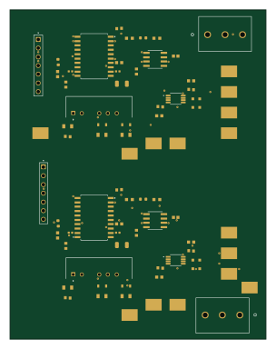
SignalGen Electrical Draft
74.7 × 95.9 mm77 parts2LNo license1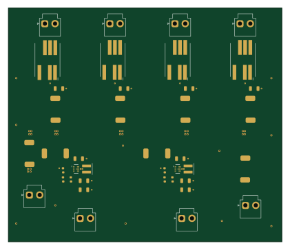
Shared regulated 5V power adapter
105 × 90 mm40 parts2LNo license1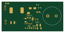
Boost Electrical Draft
54.2 × 26.5 mm25 parts2LNo license1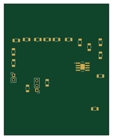
HowlandPump-AnishWorkBackout
56 × 70 mm19 parts2LNo license1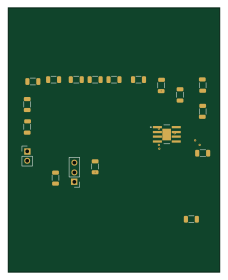
HowlandPump-AnishWork
56 × 70 mm19 parts2LNo license1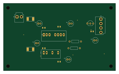
Monitor Power C1
100 × 60 mm19 parts2LNo license1
HowlandPump-AnishWorkFINAL
56 × 70 mm19 parts2LNo license1
RailSplitter Electrical Draft
50.7 × 19.4 mm12 parts2LNo license1
BuckBoost RevB
58.9 × 17 mm9 parts2LNo license1
Similar boards
 RP2040/RP2350
OSO-BOOK-C1
joeycastillo
85 × 115 mm29 parts2LCC-BY-SA-4.08.1k RP2040/RP2350
Corne cherry
foostan
277.2 × 107.5 mm164 parts2LCC-BY-4.07.7k RP2040/RP2350
Corne chocolate
277.2 × 107.5 mm164 parts2LCC-BY-4.07.7k RP2040/RP2350
Jitx design
gusmanb
55.5 × 65 mm26 parts4LGPL-3.05.0k RP2040/RP2350
LogicAnalyzer
57 × 55.2 mm6 parts2LGPL-3.05.0k RP2040/RP2350
Main
google
98 × 71 mm102 parts2LApache-2.02.9k