
Channel Monitor C1

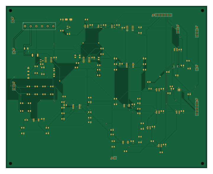
About the Channel Monitor C1 PCB
Channel Monitor C1 is an open source PCB design by AnishLanka, published on GitHub. It is a 2-layer board measuring 180 × 145 mm, with 137 components from 57 distinct parts.
Other key parts include the OPA2192ID, REF5040AID, TLV1704IPWR, SN74LVC1G74DCUR and TPS3808G33DBVR. By type, the board carries 82 resistors, 23 capacitors, 19 ICs, 9 connectors, 2 diodes and 1 transistor.
It belongs with the power & battery and test & measurement designs in this gallery.
From the project
By Pythagoras Carayannopoulos, Peter Zhao and Anish Lanka. Presentation: docs/PrototypeDemo2.pdf
By Pythagoras Carayannopoulos, Peter Zhao and Anish Lanka. Presentation: docs/PrototypeDemo2.pdf
Start with docs/RevCRelease/READMEFIRST.txt and docs/RevCRelease/IntegrationGuide.html`. Upload each board's manufacturing ZIP to JLCPCB as a separate bare PCB design. Do not upload the complete release archive as one PCB.
The signal generator sets the shape of the stimulation current. The power path provides the energy and voltage to push it. The two paths meet at the Howland, which turns the voltage command into a current.
Main components on the Channel Monitor C1
Channel Monitor C1 bill of materials (BOM)
137 components, 57 distinct parts — part numbers from the project's BOM.
| Qty | Part | Footprint | Refs |
|---|---|---|---|
| 2 | OPA2192ID OPA2192 | SOIC-8_3.9x4.9mm_P1.27mm | U1, U2 |
| 1 | REF5040AID REF5040A | SOIC-8_3.9x4.9mm_P1.27mm | U3 |
| 2 | TLV1704IPWR TLV1704 | TSSOP-14_4.4x5mm_P0.65mm | U4, U11 |
| 1 | SN74LVC1G74DCUR SN74LVC1G74 | VSSOP-8_2.3x2mm_P0.5mm | U5 |
| 1 | TPS3808G33DBVR TPS3808G33 | SOT-23-6 | U6 |
| 1 | TPS3808G50DBVR TPS3808G50 | SOT-23-6 | U7 |
| 3 | TLV1702IDGKR TLV1702 | VSSOP-8_3x3mm_P0.65mm | U8, U12, U13 |
| 4 | TPS3808G01DBVR TPS3808G01 | SOT-23-6 | U9, U14, U15, U101 |
| 1 | TPS3431SDRBR TPS3431 | Texas_DRB0008A | U10 |
| 1 | SN74LVC2G17DBVR SN74LVC2G17 | SOT-23-6 | U16 |
| 1 | SN74LVC1G08DBVR SN74LVC1G08 | SOT-23-5 | U102 |
| 1 | SN74LVC1G17DBVR SN74LVC1G17 Texas Instruments | SOT-23-5 | U103 |
| 1 | AO3400A Alpha & Omega Semiconductor | SOT-23 | Q101 |
| 1 | TSW-104-07-G-S ISOLATED_LOCAL_POWER Samtec | PinHeader_1x04_P2.54mm_Vertical | J1 |
| 1 | TSW-102-07-G-S HOWLAND_OUTPUT_INPUT Samtec | PinHeader_1x02_P2.54mm_Vertical | J2 |
| 1 | TSW-106-07-G-S ISOLATED_CONTROL Samtec | PinHeader_1x06_P2.54mm_Vertical | J3 |
| 1 | TSW-102-07-G-S HOWLAND_ENABLE Samtec | PinHeader_1x02_P2.54mm_Vertical | J4 |
| 1 | TSW-107-07-G-S SIMULTANEOUS_ADC_MODULE Samtec | PinHeader_1x07_P2.54mm_Vertical | J5 |
| 1 | TSW-103-07-G-S FAULT_STATUS Samtec | PinHeader_1x03_P2.54mm_Vertical | J6 |
| 1 | TSW-103-07-G-S HV_RAIL_MONITOR Samtec | PinHeader_1x03_P2.54mm_Vertical | J7 |
Show 37 more
| Qty | Part | Footprint | Refs |
|---|---|---|---|
| 1 | TSW-102-07-G-S COMMAND_MONITOR Samtec | PinHeader_1x02_P2.54mm_Vertical | J8 |
| 1 | TSW-102-07-G-S EXTERNAL_DUMMY_LOAD Samtec | PinHeader_1x02_P2.54mm_Vertical | J101 |
| 1 | 104-2-A-5/2 DPST_NO_5V Pickering | Pickering104_Package4_6Pin_P5.08 | K101 |
| 1 | BAV199,215 BAV199 | SOT-23 | D1 |
| 1 | SMAJ12A-E3/61 SMAJ12A_COIL_CLAMP Vishay | D_SMA | D101 |
| 16 | 885012207098 100n Wurth Elektronik | C_0805_2012Metric | C1, C2, C3, C4, C5, C6, C7, C8 +8 |
| 2 | 885012207078 1u Wurth Elektronik | C_0805_2012Metric | C11, C12 |
| 1 | C2012X5R1E226M125AC 22u 25V X5R TDK | C_0805_2012Metric | C13 |
| 3 | 885012207098 100n50V Wurth Elektronik | C_0805_2012Metric | C101, C102, C104 |
| 1 | 885382207003 1u25V Wurth Elektronik | C_0805_2012Metric | C103 |
| 1 | TNPW1206100RBEEA 100R 0.1% Vishay | R_1206_3216Metric | R1 |
| 2 | TNPW080520K0BEEA 20k Vishay | R_0805_2012Metric | R2, R3 |
| 27 | TNPW080510K0BEEA 10k Vishay | R_0805_2012Metric | R4, R6, R20, R21, R22, R23, R24, R26 +19 |
| 2 | TNPW080532K4BEEA 32.4k Vishay | R_0805_2012Metric | R5, R7 |
| 16 | TNPW0805499KBEEA 499k Vishay | R_0805_2012Metric | R8, R9, R11, R12, R43, R44, R45, R46 +8 |
| 5 | TNPW080549K9BEEA 49.9k Vishay | R_0805_2012Metric | R10, R13, R47, R52, R79 |
| 2 | TNPW08055K11BEEA 5.11k Vishay | R_0805_2012Metric | R14, R16 |
| 1 | TNPW080593K1BEEA 93.1k Vishay | R_0805_2012Metric | R15 |
| 2 | TNPW080515K6BEEA 15.6k Vishay | R_0805_2012Metric | R17, R19 |
| 1 | TNPW080571K5BEEA 71.5k Vishay | R_0805_2012Metric | R18 |
| 3 | TNPW08051K00BEEA 1k Vishay | R_0805_2012Metric | R25, R37, R39 |
| 2 | TNPW0805100KBEEA 100k Vishay | R_0805_2012Metric | R27, R71 |
| 1 | TNPW0805200KBEEA 200k Vishay | R_0805_2012Metric | R28 |
| 1 | TNPW080524K9BEEA 24.9k Vishay | R_0805_2012Metric | R29 |
| 2 | TNPW080535K7BEEA 35.7k Vishay | R_0805_2012Metric | R31, R57 |
| 1 | TNPW080588K7BEEA 88.7k Vishay | R_0805_2012Metric | R33 |
| 1 | CRCW201022K1FKEF 22.1k 1% 0.75W | R_2010_5025Metric | R36 |
| 2 | TNPW0805249RBEEA 249R Vishay | R_0805_2012Metric | R38, R40 |
| 2 | CRCW1206470RFKEA 470R 1% 0.25W | R_1206_3216Metric | R41, R42 |
| 1 | TNPW08054K42BEEA 4.42k Vishay | R_0805_2012Metric | R53 |
| 1 | TNPW08053K24BEEA 3.24k Vishay | R_0805_2012Metric | R55 |
| 1 | TNPW080525K5BEEA 25.5k Vishay | R_0805_2012Metric | R59 |
| 1 | TNPW080510K8BEEA 10.8k Vishay | R_0805_2012Metric | R66 |
| 1 | TNPW0805300KBEEA 300k Vishay | R_0805_2012Metric | R70 |
| 1 | TNPW080516K9BEEA 16.9k Vishay | R_0805_2012Metric | R72 |
| 1 | TNPW080516K5BEEA 16.5k Vishay | R_0805_2012Metric | R74 |
| 1 | TNPW0805100RBEEA 100R Vishay | R_0805_2012Metric | R101 |
Channel Monitor C1 design files
The KiCad project lives in the AnishLanka/BrainStimulation repository on GitHub; these links point at the commit this page was built from.
Channel Monitor C1: common questions
How big is the Channel Monitor C1 PCB?
The Channel Monitor C1 measures 180 × 145 mm, has 2 copper layers and is 0.41116 mm thick.
How many components are on the Channel Monitor C1?
137 components, from 57 distinct parts, with part numbers taken from the project's own BOM. The full bill of materials is listed on this page.
Where can I download the Channel Monitor C1 design files?
From the AnishLanka/BrainStimulation repository on GitHub, which has the KiCad layout, the schematic and the BOM; the links under Design files point to each one.
Can I use the Channel Monitor C1 design in my own project?
The repository has no license, so all rights stay with AnishLanka. Use it as a reference, and ask the author before reusing the design.
More boards in BrainStimulation
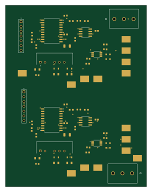
SignalGen Electrical Draft
74.7 × 95.9 mm77 parts2LNo license1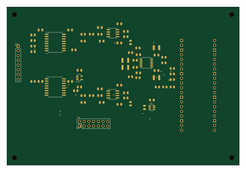 RP2040/RP2350
Channel ADC Interface RevC
125 × 85 mm69 parts2LNo license1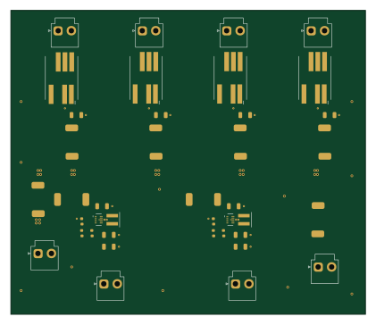
Shared regulated 5V power adapter
105 × 90 mm40 parts2LNo license1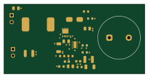
Boost Electrical Draft
54.2 × 26.5 mm25 parts2LNo license1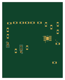
HowlandPump-AnishWork
56 × 70 mm19 parts2LNo license1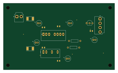
Monitor Power C1
100 × 60 mm19 parts2LNo license1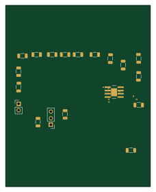
HowlandPump-AnishWorkFINAL
56 × 70 mm19 parts2LNo license1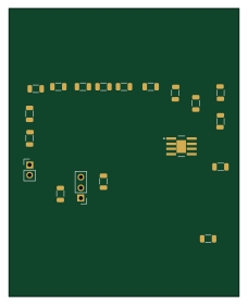
HowlandPump-AnishWorkBackout
56 × 70 mm19 parts2LNo license1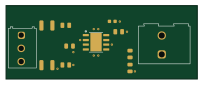
RailSplitter Electrical Draft
50.7 × 19.4 mm12 parts2LNo license1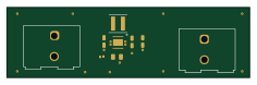
BuckBoost RevB
58.9 × 17 mm9 parts2LNo license1
Similar boards
StackLink
gusmanb
52.3 × 10.5 mm5 parts2LGPL-3.05.0k
AnalyzerBoxPCB fork
52.7 × 47.9 mm54 parts4LGPL-3.05.0k
LevelShifter
28.3 × 39.8 mm21 parts2LGPL-3.05.0k
EinkPDA screen
TalismanDesign
95 × 54 mm27 parts2LApache-2.02.0k
Stack chan
stack-chan
50 × 50 mm33 parts2LApache-2.01.7k
Display Carrier
AxxAxx
35.6 × 58.2 mm5 parts2LGPL-3.01.7k