
Audio latency tester board

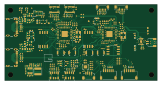
About the Audio latency tester board
Audio latency tester board is an open source RP2040/RP2350 PCB design by antmicro, published on GitHub under the Apache-2.0 license. It is a 4-layer board measuring 80 × 40 mm, with 201 components from 46 distinct parts.
Its main chip is the RP2040, from the RP2040/RP2350 family. Other key parts include the TPD4E05U06QDQARQ1, TPD4E02B04DQAR, W25Q128JVSIQ, AP62301WU-7 and AP22652W6-7. By type, the board carries 86 resistors, 55 capacitors, 21 ICs, 12 connectors, 11 diodes and 6 transistors.
It belongs with the audio designs in this gallery.
From the project
This project contains open hardware design files for an audio latency processing board. The system allows driving an external speaker and collecting audio samples from a pair of PDM or I2S microphones. The board was designed to work with a host processing platform that generates
This project contains open hardware design files for an audio latency processing board. The system allows driving an external speaker and collecting audio samples from a pair of PDM or I2S microphones. The board was designed to work with a host processing platform that generates playback and processes the captured audio samples.
The design files were prepared in KiCad 8.x.
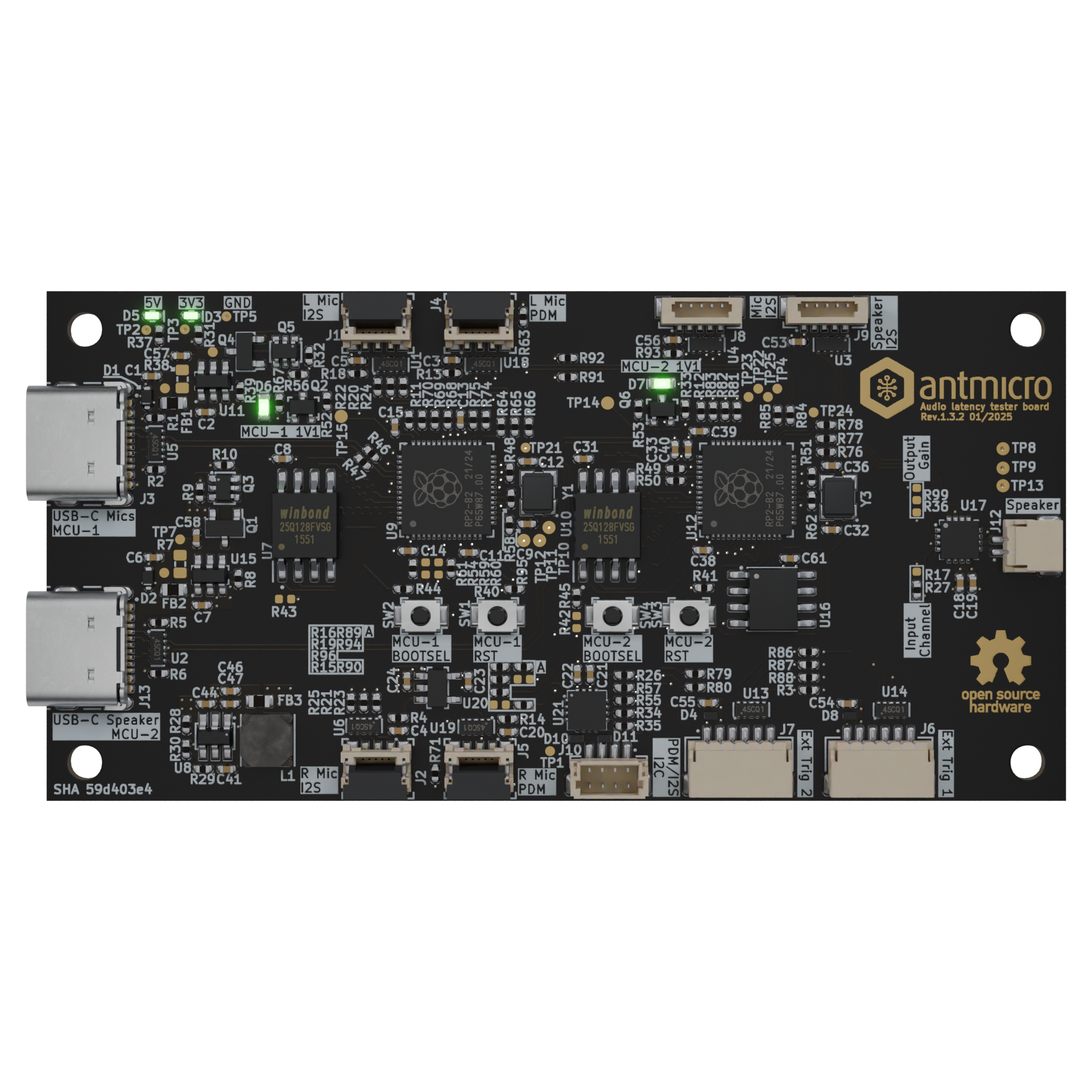
Main components on the Audio latency tester board
Audio latency tester board bill of materials (BOM)
201 components, 46 distinct parts.
| Qty | Part | Footprint | Refs |
|---|---|---|---|
| 8 | TPD4E05U06QDQARQ1 Texas Instruments | USON-10_2.5x1mm_P0.5mm | U1, U2, U5, U6, U13, U14, U18, U19 |
| 2 | TPD4E02B04DQAR TPD4E02B04DQA Texas Instruments | USON-10_2.5x1mm_P0.5mm | U3, U4 |
| 2 | W25Q128JVSIQ W25Q128JVSIQ_SOIC-8 Winbond | SOIC-8_5.3x5.3x2mm_P1.27mm | U7, U10 |
| 1 | AP62301WU-7 AP62301_TSOT Diodes Incorporated | TSOT23-6 | U8 |
| 2 | RP2040 Raspberry Pi | QFN-56-1EP_7x7mm_P0.4mm_EP3.2x3.2mm | U9, U12 |
| 2 | AP22652W6-7 AP22652W6 Diodes Incorporated | SOT-23-6 | U11, U15 |
| 1 | IS66WVS4M8BLL-104NLI ISSI | SOIC-8_3.9x4.9x1.75mm_P1.27mm | U16 |
| 1 | MAX98357AETE+T MAX98357A Analog Devices | TQFN-16-1EP_3x3mm_P0.5mm | U17 |
| 1 | TLV73318PDBVT Texas Instruments | SOT-23-5 | U20 |
| 1 | ADAU7118ACPZRL Analog Devices | VQFN-16-1EP_3x3mm_P0.5mm_EP1.68x1.68mm | U21 |
| 2 | SSM3J332R,LF SSM3J332R Toshiba | SOT-23-3 | Q1, Q4 |
| 2 | BC817-25W,115 BC817-25W Nexperia | SOT-323 | Q2, Q6 |
| 2 | BCM857BS-7-F Diodes Incorporated | SOT-363 | Q3, Q5 |
| 2 | ABM8G-12.000MHZ-18-D2Y-T Resonator_12MHz_ABM8G Abracon | Resonator_SMD_Abracon_ABM8G_3.2x2.5mm | Y1, Y3 |
| 4 | 501951-0550 Conn_FFC_Molex_5019510550 Molex | Conn_FFC_Molex_5019510550 | J1, J2, J4, J5 |
| 2 | USB4105-GF-A USB-C_GCT_USB4105-GF-A GCT | USB-C_Receptacle_GCT_USB4105-GF-A | J3, J13 |
| 2 | SM06B-SRSS-TB(LF)(SN) JST_SH_1x6_SM06B-SRSS-TB-LF-SN JST Automotive Connectors | Conn_JST_SH_1x6_SM06B-SRSS-TB-LF-SN | J6, J7 |
| 2 | BM05B-SURS-TF(LF)(SN) JST_SUR_1x5_BM05B-SURS-TB-LF-SN JST Automotive Connectors | Conn_JST_SUR_1x5_BM05B-SURS-TF-LF-SN | J8, J9 |
| 1 | BM04B-SRSS-TB(LF)(SN) JST_SH_1x4_BM04B-SRSS-TB-LF-SN JST Automotive Connectors | Conn_JST_SH_1x4_BM04B-SRSS-TB-LF-SN | J10 |
| 1 | SM02B-SRSS-TB(LF)(SN) JST_SH_1x2_SM02B-SRSS-TB-LF-SN JST Automotive Connectors | Conn_JST_SH_1x2_SM02B-SRSS-TB-LF-SN | J12 |
Show 26 more
| Qty | Part | Footprint | Refs |
|---|---|---|---|
| 4 | B3U-1000P SW_B3U-1000P_SMD Omron | SW_B3U-1000P_SMD | SW1, SW2, SW3, SW4 |
| 2 | PESD5V0X1UB,135 PESD5V0X1UB Nexperia | SOD-523 | D1, D2 |
| 2 | VLMTG1500-GS08 LED_G_0402_VLMTG1500-GS08 Vishay | LED_0402_1005Metric_G | D3, D5 |
| 5 | TPD1E0B04DPYR TPD1E0B04_XDFN-2 Texas Instruments | XDFN-2_1x0.60mm | D4, D8, D9, D10, D11 |
| 2 | KP-1608CGCK LED_G_0603_KP-1608CGCK Kingbright | LED_0603_1608Metric_G | D6, D7 |
| 3 | BLM18PG121SN1D FB_120Z_2A_Murata-BLM18PG_0603 Murata | FB_0603_1608Metric | FB1, FB2, FB3 |
| 1 | IFSC1515AHER2R2M01 L_2u2_3.1A_Vishay-IFSC-1515AH-01 Vishay | L_Vishay-IFSC-1515AH | L1 |
| 2 | GRM155R71H103KA88D C_10n_0402 Murata | C_0402_1005Metric | C1, C6 |
| 14 | GRM155R61H104KE14D C_100n_0402 Murata | C_0402_1005Metric | C2, C3, C4, C5, C7, C8, C18, C20 +6 |
| 4 | CL05C180JB51PNC C_18p_0402 Samsung Electro-Mechanics | C_0402_1005Metric | C9, C12, C32, C36 |
| 4 | C1005X6S1A105K050BC C_1u_0402 TDK | C_0402_1005Metric | C10, C33, C35, C52 |
| 25 | C0402C104J4RAC7411 C_100n_16V_X7R_0402 KEMET | C_0402_1005Metric | C11, C13, C14, C15, C16, C17, C21, C22 +17 |
| 4 | GRM155R61A106ME11D C_10u_10V_0402 Murata | C_0402_1005Metric | C19, C44, C57, C58 |
| 2 | GRM158R60J226ME01D C_22u_0402 Murata | C_0402_1005Metric | C46, C47 |
| 4 | CR0402-FX-5101GLF R_5k1_0402 Bourns | R_0402_1005Metric | R1, R2, R5, R6 |
| 44 | ERJ2GE0R00X R_0R_0402 Panasonic | R_0402_1005Metric | R3, R4, R11, R12, R13, R14, R16, R18 +36 |
| 2 | CR0402-FX-2002GLF R_20k_0402 Bourns | R_0402_1005Metric | R8, R39 |
| 6 | CR0402-FX-1002GLF R_10k_0402 Bourns | R_0402_1005Metric | R9, R10, R32, R40, R41, R56 |
| 9 | CR0402-FX-1001GLF R_1k_0402 Bourns | R_0402_1005Metric | R26, R30, R33, R37, R44, R45, R48, R51 +1 |
| 3 | CR0402-FX-1004GLF R_1M_0402 Bourns | R_0402_1005Metric | R27, R58, R62 |
| 1 | RC0402FR-073K16L R_3k16_0402 YAGEO | R_0402_1005Metric | R29 |
| 1 | CR0402-FX-2200GLF R_220R_0402 Bourns | R_0402_1005Metric | R31 |
| 4 | CR0402-FX-27R0GLF R_27R_0402 Bourns | R_0402_1005Metric | R46, R47, R49, R50 |
| 2 | CR0402-FX-2700GLF R_270R_0402 Bourns | R_0402_1005Metric | R53, R67 |
| 6 | CR0402-FX-51R0GLF R_51R_0402 Bourns | R_0402_1005Metric | R64, R65, R77, R78, R90, R95 |
| 4 | CR0402-FX-2701GLF R_2k7_0402 Bourns | R_0402_1005Metric | R79, R80, R91, R92 |
Audio latency tester board design files
The KiCad project lives in the antmicro/audio-latency-tester-board repository on GitHub; these links point at the commit this page was built from.
Audio latency tester board: common questions
What microcontroller does the Audio latency tester board use?
The Audio latency tester board is built around the RP2040, from the RP2040/RP2350 family.
How big is the Audio latency tester board?
The Audio latency tester board measures 80 × 40 mm, has 4 copper layers and is 1.6 mm thick.
How many components are on the Audio latency tester board?
201 components, from 46 distinct parts. The full bill of materials is listed on this page.
Where can I download the Audio latency tester board design files?
From the antmicro/audio-latency-tester-board repository on GitHub, which has the KiCad layout and the schematic; the links under Design files point to each one.
Can I use the Audio latency tester board design in my own project?
Yes, under the terms of its Apache-2.0 license, which antmicro chose for the repository.
Can I test firmware for the Audio latency tester board without the hardware?
Yes. HardLabs builds a simulation of the board from its netlist and BOM, so you can run and debug RP2040/RP2350 firmware against it before you order a PCB.
Similar boards
 RP2040/RP2350
Open Book Abridged Edition
joeycastillo
85 × 115 mm29 parts2LCC-BY-SA-4.08.1k RP2040/RP2350
Corne
foostan
277.2 × 107.5 mm164 parts2LCC-BY-4.07.7k RP2040/RP2350
Corne
277.2 × 107.5 mm164 parts2LCC-BY-4.07.7k RP2040/RP2350
LogicAnalyzer
gusmanb
57 × 55.2 mm6 parts2LGPL-3.05.0k RP2040/RP2350
Jitx design
55.5 × 65 mm26 parts4LGPL-3.05.0k RP2040/RP2350
Main
google
98 × 71 mm102 parts2LApache-2.02.9k