
Robocar pinky

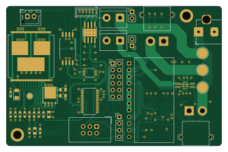
About the Robocar pinky PCB
Robocar pinky is an open source PCB design by arkorobotics, published on GitHub. It is a 4-layer board measuring 81.3 × 52.8 mm, with 83 components from 42 distinct parts.
Other key parts include the PCA9685PW, DRV8871DDAR, VNH5019ATR-E, ADS1115IDGSR and NCP1117LPST50T3G. By type, the board carries 35 resistors, 23 capacitors, 9 ICs, 8 connectors, 4 diodes and 2 switches.
It belongs with the iot & wireless and power & battery designs in this gallery.
From the project
DIY Robocar Project - Codename Pinky
For 3D printed models, use the Autodesk Fusion 360 Pinky CAD model for assembly.
For electrical assembly, see diagram below:
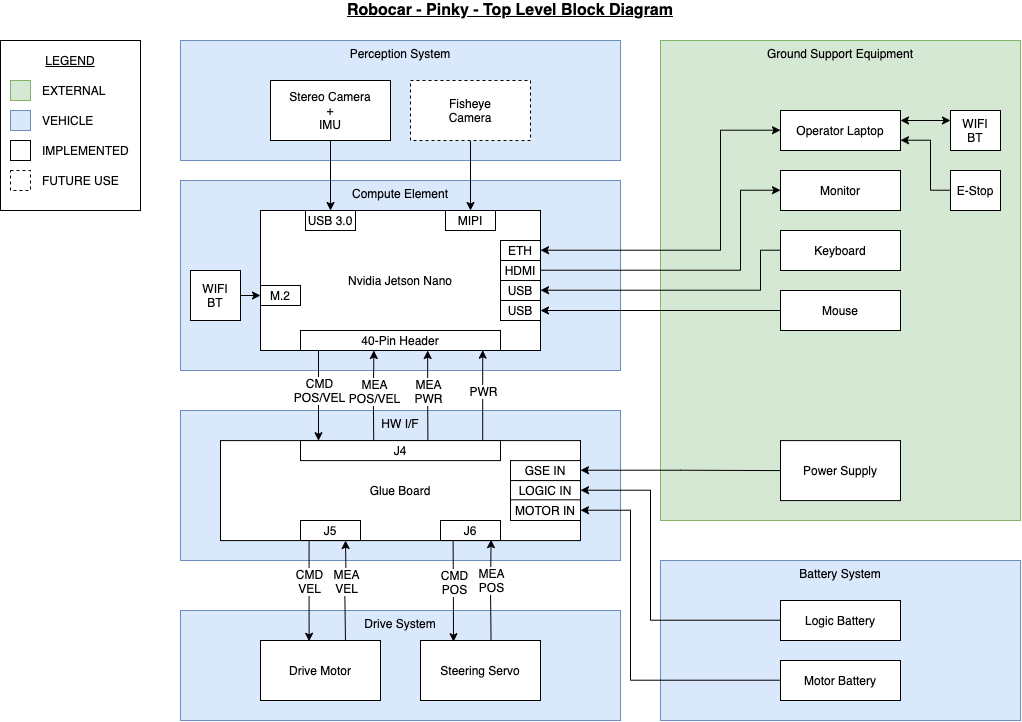
Main components on the Robocar pinky
Robocar pinky bill of materials (BOM)
83 components, 42 distinct parts — part numbers from the project's BOM.
| Qty | Part | Footprint | Refs |
|---|---|---|---|
| 1 | PCA9685PW | TSSOP-28_4.4x9.7mm_P0.65mm | U1 |
| 1 | DRV8871DDAR DRV8871DDA | Texas_HTSOP-8-1EP_3.9x4.9mm_P1.27mm_EP2.95x4.9mm_Mask2.4x3.1mm_ThermalVias | U2 |
| 1 | VNH5019ATR-E | ST_MultiPowerSO-30 | U3 |
| 1 | ADS1115IDGSR ADS1115IDGS | TSSOP-10_3x3mm_P0.5mm | U4 |
| 1 | NCP1117LPST50T3G NCP1117-5.0_SOT223 | SOT-223-3_TabPin2 | U5 |
| 1 | TPS2121RUXR | IC_TPS2121RUXR | U6 |
| 1 | AMC1301DWVR | SOIC127P1150X280-8N | U7 |
| 2 | INA260AIPW INA260 | TSSOP-16_4.4x5mm_P0.65mm | U8, U9 |
| 1 | CSD17501Q5A | TDSON-8-1 | Q1 |
| 2 | XT30PW-M Conn_01x02_Male | AMASS_XT30PW-M_1x02_P2.50mm_Horizontal | J1, J3 |
| 1 | PJ-102B Barrel_Jack | BarrelJack_Horizontal | J2 |
| 1 | 67997-112HLF Conn_02x06_Odd_Even | PinHeader_2x06_P2.54mm_Vertical | J4 |
| 1 | CONN_01X02_MALE Conn_01x02_Male | JST_XH_B2B-XH-AM_1x02_P2.50mm_Vertical | J5 |
| 1 | 530470510 Conn_01x05_Female | Molex_PicoBlade_53047-0510_1x05_P1.25mm_Vertical | J6 |
| 1 | CONN_01X04_MALE Conn_01x04_Male | PinHeader_1x04_P2.54mm_Vertical | J7 |
| 1 | SFH11-NBPC-D03-ST-BK Conn_02x03_Odd_Even | IDC-Header_2x03_P2.54mm_Vertical | J8 |
| 1 | R-745.0D | CONV_R-745.0D | PS1 |
| 1 | M2011LL1W01-G SW_SPST | TerminalBlock_bornier-2_P5.08mm | SW1 |
| 1 | M2011LL1W01-C SW_SPST | TerminalBlock_bornier-2_P5.08mm | SW2 |
| 1 | STPS5L60S | DO-214AB-SMC | D1 |
Show 22 more
| Qty | Part | Footprint | Refs |
|---|---|---|---|
| 1 | MPR3BWD LED | PinHeader_1x02_P2.54mm_Vertical | D2 |
| 1 | MPR3RD LED | PinHeader_1x02_P2.54mm_Vertical | D3 |
| 1 | LTST-C235KGKRKT LED_Dual_2pin | LED_1206_3216Metric | D4 |
| 8 | C0805C105K4RACTU 1uF | C_0805_2012Metric | C1, C2, C4, C6, C7, C17, C22, C23 |
| 3 | C1210C107M4PAC7800 100uF | C_1210_3225Metric | C3, C5, C9 |
| 3 | C0805C106K4PACTU 10uF | C_0805_2012Metric | C8, C19, C20 |
| 4 | C0805C104Z5VACTU 0.1uF | C_0805_2012Metric | C10, C12, C14, C16 |
| 3 | C0805C333K5RACTU 33nF | C_0805_2012Metric | C11, C18, C21 |
| 1 | C1210C226K3PACTU 22uF | C_0805_2012Metric | C13 |
| 1 | GRM32EC81C476KE15L 47uF | C_0805_2012Metric | C15 |
| 2 | RC0603FR-0723K7L 23.7k | R_0603_1608Metric | R1, R6 |
| 3 | CR0603-FX-4991ELF 5k | R_0603_1608Metric | R2, R5, R7 |
| 1 | RC0603FR-072K61L 2.6k | R_0603_1608Metric | R3 |
| 1 | RC0603FR-0710K2L 10.2k | R_0603_1608Metric | R4 |
| 1 | RC0603FR-0718K7L 18.7k | R_0603_1608Metric | R8 |
| 1 | ESR03EZPJ470 47R | R_0603_1608Metric | R9 |
| 1 | ESR03EZPJ471 470 | R_0603_1608Metric | R10 |
| 14 | RC0603FR-0710KL 10k | R_0603_1608Metric | R11, R12, R13, R19, R26, R31, R32, R33 +6 |
| 6 | RC0603JR-071KL 1k | R_0603_1608Metric | R20, R21, R22, R23, R24, R28 |
| 3 | ERJ-3EKF4751V 4.7k | R_0603_1608Metric | R25, R27, R30 |
| 1 | ERA-3AEB303V 30K | R_0603_1608Metric | R29 |
| 1 | ESR03EZPJ471 470R | R_0603_1608Metric | R35 |
Robocar pinky design files
The KiCad project lives in the arkorobotics/robocar-pinky repository on GitHub; these links point at the commit this page was built from.
Robocar pinky: common questions
How big is the Robocar pinky PCB?
The Robocar pinky measures 81.3 × 52.8 mm, has 4 copper layers and is 1.6 mm thick.
How many components are on the Robocar pinky?
83 components, from 42 distinct parts, with part numbers taken from the project's own BOM. The full bill of materials is listed on this page.
Where can I download the Robocar pinky design files?
From the arkorobotics/robocar-pinky repository on GitHub, which has the KiCad layout and the BOM; the links under Design files point to each one.
Can I use the Robocar pinky design in my own project?
The repository has no license, so all rights stay with arkorobotics. Use it as a reference, and ask the author before reusing the design.
Similar boards

Stack chan
stack-chan
50 × 50 mm33 parts2LApache-2.01.7k
Display Carrier
AxxAxx
35.6 × 58.2 mm5 parts2LGPL-3.01.7k
ControllerCurrentShuntAddOn
stuartpittaway
26 × 16.9 mm9 parts2LCC-BY-NC-4.01.1k
Module 16S PassiveBalanceAddOn
61 × 74 mm86 parts2LCC-BY-NC-4.01.1k
TemperaturePCB PANEL
116 × 75.5 mm178 parts2LCC-BY-NC-4.01.1k
ProgrammingAdapter
10.5 × 83 mm3 parts2LCC-BY-NC-4.01.1k