
RoboMausV2

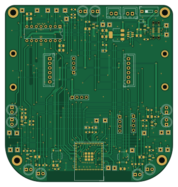
About the RoboMausV2 PCB
RoboMausV2 is an open source ESP32 PCB design by Arne-Berner, published on GitHub. It is a 4-layer board measuring 90 × 95 mm, with 100 components from 34 distinct parts.
Its main chip is the ESP32-S3-MINI-1, from the ESP32 family. Other key parts include the AMS1117-3.3, L293D and USBLC6-2SC6. By type, the board carries 31 resistors, 14 capacitors, 9 diodes, 7 connectors, 6 transistors and 4 ICs.
It belongs with the iot & wireless, displays & leds and sensors designs in this gallery.
From the project
This is another try at using the esp32s3 with rust and some electronics to create life! Or at least solve a maze.
That being said I also wanted to use my 3D printer more and get rid of that fear that accompanies anything new. Doing this project I feel like I will be able to create electronic devices much more easily in the future. Not only because I learned some tricks on my way, but because I simply have done it before.
Later on it feels like "read the datasheet" really was the solution to most problems. But only seemingly so. Experts don't read the full datasheet, even if it is only a few pages long. They won't look at all the data. But they know how to skim the datasheet for the most important info…
Main components on the RoboMausV2
RoboMausV2 bill of materials (BOM)
100 components, 34 distinct parts.
| Qty | Part | Footprint | Refs |
|---|---|---|---|
| 1 | AMS1117-3.3 | SOT-223-3_TabPin2 | U1 |
| 1 | L293D | DIP-16_W7.62mm | U2 |
| 1 | ESP32-S3-MINI-1 | ESP32-S2-MINI-1 | U3 |
| 1 | USBLC6-2SC6 | SOT-23-6 | U4 |
| 1 | AO3401A | SOT-23 | Q1 |
| 5 | 2N7002 | SOT-23 | Q2, Q3, Q4, Q5, Q6 |
| 2 | JST-XH | JST_XH_B2B-XH-A_1x02_P2.50mm_Vertical | J1, J2 |
| 1 | Color_Pins | PinHeader_1x04_P2.54mm_Vertical | J3 |
| 1 | Gyro_Pins | PinHeader_1x04_P2.54mm_Vertical | J4 |
| 1 | left_motor_connector | JST_XH_B6B-XH-A_1x06_P2.50mm_Vertical | J5 |
| 1 | right_motor_connector | JST_XH_B6B-XH-A_1x06_P2.50mm_Vertical | J6 |
| 1 | USB4145-03-0230-C_REVA2 | GCT_USB4145-03-0230-C_REVA2 | J7 |
| 23 | Testpoint | TestPoint_THTPad_2.0x2.0mm_Drill1.0mm | 3.3, GND1, GPIO1, GPIO2, GPIO3, GPIO4, GPIO5, GPIO6 +15 |
| 1 | Battery | TestPoint_THTPad_2.0x2.0mm_Drill1.0mm | Bat1 |
| 2 | 2.54MaleDupon | PinHeader_1x04_P2.54mm_Vertical | JTAG1, UART1 |
| 1 | Battery_SW | SW_DIP_SPSTx01_Slide_9.78x4.72mm_W7.62mm_P2.54mm | SW1 |
| 1 | SW_Enable | SW_Push_1P1T_XKB_TS-1187A | SW2 |
| 1 | SW_Boot | SW_Push_1P1T_XKB_TS-1187A | SW3 |
| 1 | RED | LED_0603_1608Metric_Pad1.05x0.95mm_HandSolder | D1 |
| 1 | 1N4148WS | D_SOD-323 | D2 |
Show 14 more
| Qty | Part | Footprint | Refs |
|---|---|---|---|
| 5 | IR | LED_D5.0mm_IRGrey | D3, D4, D5, D6, D7 |
| 1 | GREEN | LED_0603_1608Metric_Pad1.05x0.95mm_HandSolder | D8 |
| 1 | BLUE | LED_0603_1608Metric_Pad1.05x0.95mm_HandSolder | D9 |
| 10 | 0.1uF | C_0805_2012Metric_Pad1.18x1.45mm_HandSolder | C1, C3, C4, C5, C6, C7, C11, C13 +2 |
| 2 | 10uF | C_0805_2012Metric_Pad1.18x1.45mm_HandSolder | C2, C10 |
| 2 | 4.7uF | C_0805_2012Metric_Pad1.18x1.45mm_HandSolder | C8, C9 |
| 4 | 0603WAF5101T5E 5.1k | R_0603_1608Metric_Pad0.98x0.95mm_HandSolder | R1, R28, R29, R30 |
| 1 | 0603WAF3301T5E 3.3k | R_0603_1608Metric_Pad0.98x0.95mm_HandSolder | R2 |
| 5 | R_Photo | LED_D5.0mm_IRBlack | R3, R5, R7, R9, R11 |
| 5 | 1.8k Ohm | R_0603_1608Metric_Pad0.98x0.95mm_HandSolder | R4, R6, R8, R10, R12 |
| 5 | 100 Ohm | R_0603_1608Metric_Pad0.98x0.95mm_HandSolder | R13, R16, R19, R22, R25 |
| 5 | 47k Ohm | R_0603_1608Metric_Pad0.98x0.95mm_HandSolder | R14, R17, R20, R23, R26 |
| 5 | 51 Ohm | R_0603_1608Metric_Pad0.98x0.95mm_HandSolder | R15, R18, R21, R24, R27 |
| 1 | 0603WAF3301T5E 10k | R_0603_1608Metric_Pad0.98x0.95mm_HandSolder | R32 |
RoboMausV2 design files
The KiCad project lives in the Arne-Berner/RoboMausV2 repository on GitHub; these links point at the commit this page was built from.
- LayoutRoboMaus.kicad_pcb
- SchematicRoboMaus.kicad_sch
RoboMausV2: common questions
What microcontroller does the RoboMausV2 use?
The RoboMausV2 is built around the ESP32-S3-MINI-1, from the ESP32 family.
How big is the RoboMausV2 PCB?
The RoboMausV2 measures 90 × 95 mm, has 4 copper layers and is 1.6 mm thick.
How many components are on the RoboMausV2?
100 components, from 34 distinct parts. The full bill of materials is listed on this page.
Where can I download the RoboMausV2 design files?
From the Arne-Berner/RoboMausV2 repository on GitHub, which has the KiCad layout and the schematic; the links under Design files point to each one.
Can I use the RoboMausV2 design in my own project?
The repository has no license, so all rights stay with Arne-Berner. Use it as a reference, and ask the author before reusing the design.
Can I test firmware for the RoboMausV2 without the hardware?
Yes. HardLabs builds a simulation of the board from its netlist and BOM, so you can run and debug ESP32 firmware against it before you order a PCB.
Similar boards
 ESP32
OSO-BOOK-B1
joeycastillo
85 × 115 mm65 parts2LCC-BY-SA-4.08.1k ESP32
Powertrain
byrantech
64 × 45.4 mm171 parts4LMIT4.3k ESP32
Badge
atopile
56.3 × 39 mm239 parts4LMIT4.0k ESP32
Esp32 minimal
36.2 × 26.8 mm20 parts2LMIT4.0k ESP32
Racer
StuckAtPrototype
36 × 50.2 mm70 parts4LApache-2.03.8k ESP32
Controller
29 × 74 mm58 parts4LApache-2.03.8k