
Nodo BMS

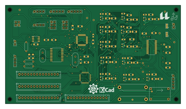
About the Nodo BMS PCB
Nodo BMS is an open source AVR/Arduino PCB design by AugustoS97, published on GitHub under the GPL-3.0 license. It is a 2-layer board measuring 149.2 × 83.7 mm, with 107 components from 43 distinct parts.
Its main chip is the ATMEGA328P-PU, from the AVR/Arduino family. Other key parts include the ADG731, MCP2515-XSO, TJA1050T, LTC6804-2 and MP2307. By type, the board carries 46 resistors, 24 capacitors, 15 connectors, 12 transistors, 6 ICs and 2 crystals.
It belongs with the power & battery designs in this gallery.
From the project
Repositorio con el diseño de un BMS y una batería como TFM
In the present Master’s Degree Final Project, a Battery Management System (BMS) has been designed and manufactured, as well as a modular battery configurable at different voltages and capacities, with the aim of being able to power isolated electronic systems such as devices for capturing eco-acoustic significance indexes. The electronic design of the different modules that make up the power supply and management system has been carried out, as well as the calculation and design of the battery based on lithium-ion cells and its mechanical structure. In order to be able to supply this system…
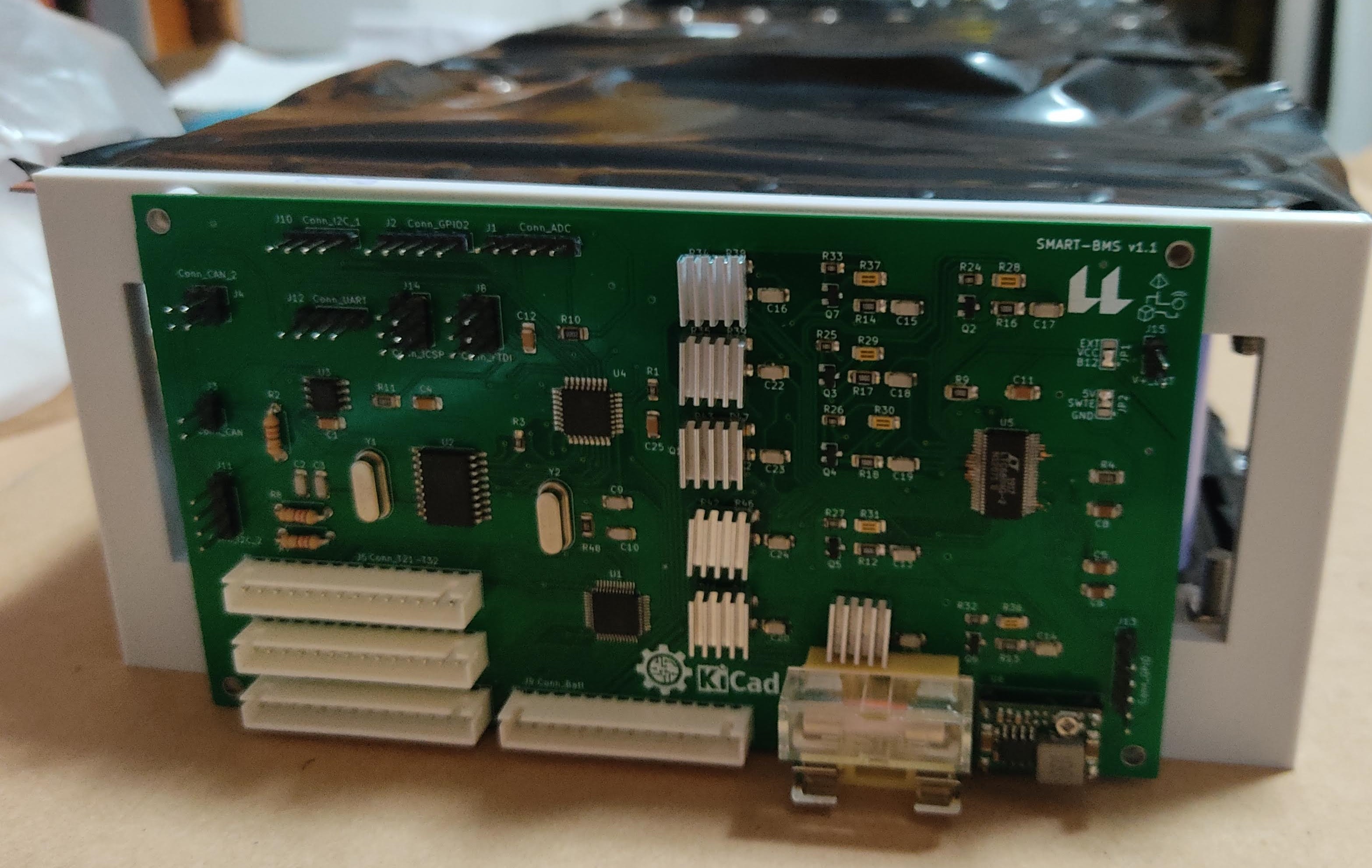
Main components on the Nodo BMS
Nodo BMS bill of materials (BOM)
107 components, 43 distinct parts — part numbers from the project's BOM.
| Qty | Part | Footprint | Refs |
|---|---|---|---|
| 1 | ADG731 | TQFP-48_7x7mm_P0.5mm | U1 |
| 1 | MCP2515-XSO MCP2515-xSO | SOIC-18W_7.5x11.6mm_P1.27mm | U2 |
| 1 | TJA1050T | SOIC-8_3.9x4.9mm_P1.27mm | U3 |
| 1 | ATMEGA328P-PU ATmega328P-PU | TQFP-32_7x7mm_P0.8mm | U4 |
| 1 | LTC6804-2 | SSOP-48_5.3x12.8mm_P0.5mm | U5 |
| 1 | MP2307 | MP2307 | U6 |
| 12 | BSS308PE | SOT-23 | Q2, Q3, Q4, Q5, Q6, Q7, Q8, Q9 +4 |
| 1 | 8MHZ 8MHz | Crystal_HC49-4H_Vertical | Y1 |
| 1 | 16MHZ 16MHz | Crystal_HC49-4H_Vertical | Y2 |
| 1 | Conn_ADC | PinHeader_1x05_P2.54mm_Vertical | J1 |
| 1 | CONN_GPIO2 Conn_GPIO2 | PinHeader_1x05_P2.54mm_Vertical | J2 |
| 1 | Conn_CAN | PinHeader_1x02_P2.54mm_Vertical | J3 |
| 1 | CONN_CAN_2 Conn_CAN_2 | PinSocket_2x02_P2.54mm_Vertical | J4 |
| 1 | CONN_T21-T32 Conn_T21-T32 | JST_XH_B14B-XH-A_1x14_P2.50mm_Vertical | J5 |
| 1 | CONN_T1-T10 Conn_T1-T10 | JST_XH_B14B-XH-A_1x14_P2.50mm_Vertical | J6 |
| 1 | CONN_T11-T20 Conn_T11-T20 | JST_XH_B14B-XH-A_1x14_P2.50mm_Vertical | J7 |
| 1 | Conn_FTDI | PinHeader_2x03_P2.54mm_Vertical | J8 |
| 1 | Conn_Batt | JST_XH_B14B-XH-A_1x14_P2.50mm_Vertical | J9 |
| 1 | CONN_I2C_1 Conn_I2C_1 | PinHeader_1x04_P2.54mm_Vertical | J10 |
| 1 | CONN_I2C_2 Conn_I2C_2 | PinHeader_1x04_P2.54mm_Vertical | J11 |
Show 23 more
| Qty | Part | Footprint | Refs |
|---|---|---|---|
| 1 | Conn_UART | PinHeader_1x04_P2.54mm_Vertical | J12 |
| 1 | Conn_GPIO | PinHeader_1x05_P2.54mm_Vertical | J13 |
| 1 | Conn_ICSP | PinHeader_2x03_P2.54mm_Vertical | J14 |
| 1 | V+_EXT | PinHeader_1x02_P2.54mm_Vertical | J15 |
| 1 | fuse 1A | Fuseholder_Cylinder-5x20mm_Stelvio-Kontek_PTF78_Horizontal_Open | F1 |
| 1 | fuse 0,5 A | Fuseholder_Cylinder-5x20mm_Stelvio-Kontek_PTF78_Horizontal_Open | F2 |
| 3 | 100N 100n | R_1206_3216Metric_Pad1.30x1.75mm_HandSolder | C1, C4, C11 |
| 2 | 27PF 27pF | R_1206_3216Metric_Pad1.30x1.75mm_HandSolder | C2, C3 |
| 3 | 1u | R_1206_3216Metric_Pad1.30x1.75mm_HandSolder | C5, C6, C8 |
| 1 | 12-22 pF | R_1206_3216Metric_Pad1.30x1.75mm_HandSolder | C9 |
| 1 | 12-22PF 12-22pF | R_1206_3216Metric_Pad1.30x1.75mm_HandSolder | C10 |
| 1 | 100NF 100nF | R_1206_3216Metric_Pad1.30x1.75mm_HandSolder | C12 |
| 12 | 10N 10n | R_1206_3216Metric_Pad1.30x1.75mm_HandSolder | C13, C14, C15, C16, C17, C18, C19, C20 +4 |
| 1 | 100NF 100nF | R_1206_3216Metric | C25 |
| 2 | 10K 10k | R_0805_2012Metric_Pad1.15x1.40mm_HandSolder | R1, R3 |
| 3 | 120R | R_Axial_DIN0207_L6.3mm_D2.5mm_P7.62mm_Horizontal | R2, R7, R8 |
| 1 | 5k | R_1206_3216Metric_Pad1.42x1.75mm_HandSolder | R4 |
| 13 | 100R | R_1206_3216Metric_Pad1.30x1.75mm_HandSolder | R9, R12, R13, R14, R15, R16, R17, R18 +5 |
| 1 | 10K 10k | R_1206_3216Metric_Pad1.30x1.75mm_HandSolder | R10 |
| 1 | 1k | R_1206_3216Metric_Pad1.30x1.75mm_HandSolder | R11 |
| 12 | 1k | R_0805_2012Metric_Pad1.15x1.40mm_HandSolder | R24, R25, R26, R27, R32, R33, R34, R35 +4 |
| 12 | 10R, 2W | R_1206_3216Metric_Pad1.30x1.75mm_HandSolder | R28, R29, R30, R31, R36, R37, R38, R39 +4 |
| 1 | 1M | R_1206_3216Metric | R48 |
Nodo BMS design files
The KiCad project lives in the AugustoS97/BMS-BatterySystem repository on GitHub; these links point at the commit this page was built from.
Nodo BMS: common questions
What microcontroller does the Nodo BMS use?
The Nodo BMS is built around the ATMEGA328P-PU, from the AVR/Arduino family.
How big is the Nodo BMS PCB?
The Nodo BMS measures 149.2 × 83.7 mm, has 2 copper layers and is 1.6 mm thick.
How many components are on the Nodo BMS?
107 components, from 43 distinct parts, with part numbers taken from the project's own BOM. The full bill of materials is listed on this page.
Where can I download the Nodo BMS design files?
From the AugustoS97/BMS-BatterySystem repository on GitHub, which has the KiCad layout and the BOM; the links under Design files point to each one.
Can I use the Nodo BMS design in my own project?
Yes, under the terms of its GPL-3.0 license, which AugustoS97 chose for the repository.
Can I test firmware for the Nodo BMS without the hardware?
Yes. HardLabs builds a simulation of the board from its netlist and BOM, so you can run and debug AVR/Arduino firmware against it before you order a PCB.
More boards in BMS-BatterySystem
Similar boards
 AVR/Arduino
Redox keyboard
mattdibi
162.2 × 126.5 mm77 parts2LMIT2.0k AVR/Arduino
ModuleV450
stuartpittaway
30 × 61.4 mm39 parts2LCC-BY-NC-4.01.1k AVR/Arduino
V4
30 × 50 mm38 parts2LCC-BY-NC-4.01.1k AVR/Arduino
Discipline
coseyfannitutti
304.9 × 122.8 mm170 parts2LCC-BY-NC-4.01.0k AVR/Arduino
Megadesk
gcormier
41.7 × 32.2 mm23 parts2LGPL-3.0818 AVR/Arduino
Easyduino Atmega Nano
Hanqaqa
43.4 × 18 mm30 parts4LCERN-OHL-P-2.0746