
Flipper thermal camera

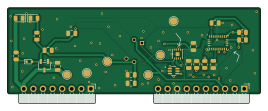
About the Flipper thermal camera PCB
Flipper thermal camera is an open source PCB design by Badbird5907, published on GitHub. It is a 2-layer board measuring 67 × 25.3 mm, with 26 components from 20 distinct parts.
Other key parts include the VEML7700-TT, MLX90640ESF-BAB-000-SP, XC6206PxxxMR, BNO055 and SHT31-DIS. By type, the board carries 9 capacitors, 6 ICs, 6 resistors, 3 diodes and 2 connectors.
It belongs with the sensors designs in this gallery.
From the project
This is a thermal camera module for the Flipper Zero!
This is a thermal camera module for the Flipper Zero!
It uses the MLX90640 thermal sensor, with a whopping resolution of 32x24, and a suite of other auxiliary sensors, including: - VEML7700 Light Sensor - ICM-20948 IMU - SHT31 Temperature & Humidity Sensor
All 4 sensors communicate to the flipper via it's I2C bus.
Why no case? Most flipper PCB mods don't use a case to show off the PCB. I think it especially goes better with my flipper as it has a clear case mod.
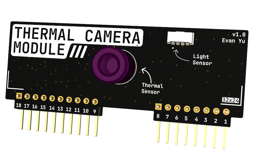
Main components on the Flipper thermal camera
Flipper thermal camera bill of materials (BOM)
26 components, 20 distinct parts — part numbers from the project's BOM.
| Qty | Part | Footprint | Refs |
|---|---|---|---|
| 1 | VEML7700-TT | XDCR_VEML7700-TT | IC1 |
| 1 | MLX90640ESF-BAB-000-SP | TO292P945H1165-4 | U1 |
| 1 | XC6206PxxxMR | SOT-23-3 | U2 |
| 1 | BNO055 | LGA-28_5.2x3.8mm_P0.5mm | U3 |
| 1 | SHT31-DIS | Sensirion_DFN-8-1EP_2.5x2.5mm_P0.5mm_EP1.1x1.7mm | U4 |
| 1 | SP1001-05JTG | SOP65P220X110-6N | U6 |
| 1 | Conn_01x08 | PinHeader_1x08_P2.54mm_Horizontal | J1 |
| 1 | Conn_01x10 | PinHeader_1x10_P2.54mm_Horizontal | J2 |
| 1 | LED_R | LED_0805_2012Metric | D1 |
| 1 | LED_G | LED_0805_2012Metric | D2 |
| 1 | RB521S-30 | D_SOD-523 | D3 |
| 1 | 120nF | C_0805_2012Metric | C1 |
| 3 | 100nF | C_0805_2012Metric | C2, C4, C7 |
| 2 | 1uF | C_0805_2012Metric | C3, C5 |
| 1 | 4.7uF | C_0805_2012Metric | C6 |
| 2 | 10uF | C_0805_2012Metric | C8, C9 |
| 2 | 2.2k | R_0805_2012Metric | R1, R2 |
| 1 | 1.5k | R_0805_2012Metric | R3 |
| 2 | 10k | R_0805_2012Metric | R4, R5 |
| 1 | 330 | R_0805_2012Metric | R6 |
Flipper thermal camera design files
The KiCad project lives in the Badbird5907/flipper-thermal-camera repository on GitHub; these links point at the commit this page was built from.
Flipper thermal camera: common questions
How big is the Flipper thermal camera PCB?
The Flipper thermal camera measures 67 × 25.3 mm, has 2 copper layers and is 1.6 mm thick.
How many components are on the Flipper thermal camera?
26 components, from 20 distinct parts, with part numbers taken from the project's own BOM. The full bill of materials is listed on this page.
Where can I download the Flipper thermal camera design files?
From the Badbird5907/flipper-thermal-camera repository on GitHub, which has the KiCad layout, the schematic and the BOM; the links under Design files point to each one.
Can I use the Flipper thermal camera design in my own project?
The repository has no license, so all rights stay with Badbird5907. Use it as a reference, and ask the author before reusing the design.
Similar boards
Sensor smd
scottbez1
40 × 20 mm5 parts2LApache-2.04.2k
Sensors
StuckAtPrototype
15.2 × 9 mm14 parts4LApache-2.03.8k
Microphone
Mentra-Community
5.5 × 6.1 mm6 parts2LMIT1.2k
TemperaturePCB PANEL
stuartpittaway
116 × 75.5 mm178 parts2LCC-BY-NC-4.01.1k
Pots
shanteacontrols
390 × 93 mm75 parts2LApache-2.0956
USB
52 × 12.6 mm6 parts2LApache-2.0956