
MRIRobot

About the MRIRobot PCB
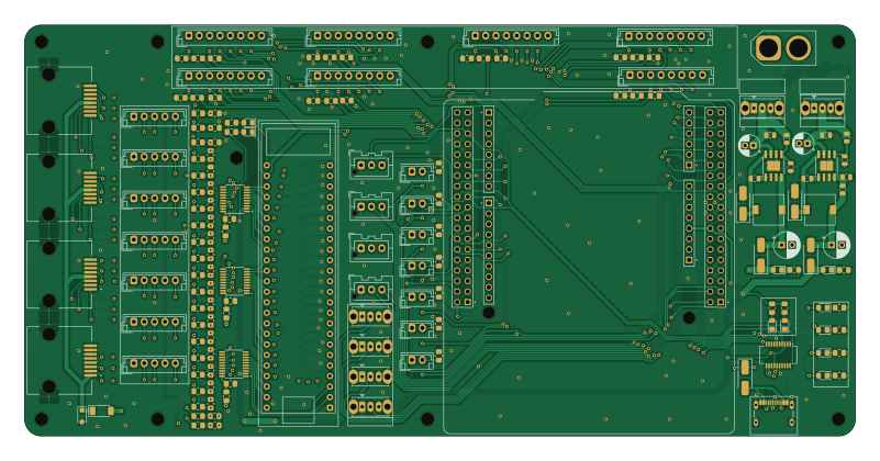
MRIRobot is an open source PCB design by biomimetics, published on GitHub. It is a 4-layer board measuring 200 × 99 mm, with 330 components from 49 distinct parts.
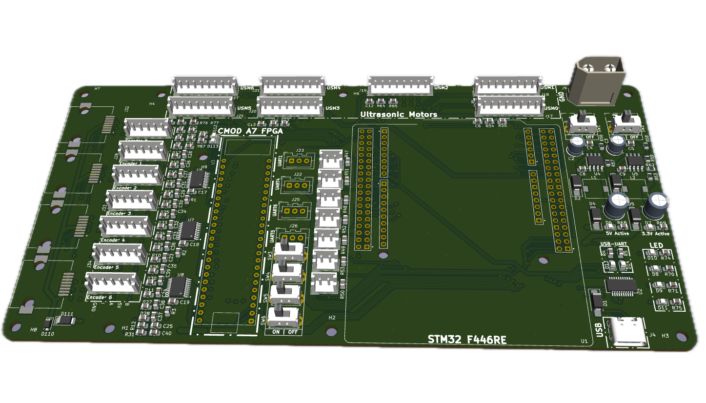
Other key parts include the NUCLEO-F446RE, FT231XS, CMOD_A7_FPGA, LM22676MR-5 and LM22676MR-ADJ. By type, the board carries 113 diodes, 108 resistors, 61 capacitors, 31 connectors, 8 ICs and 6 switches.
It belongs with the robotics & motion designs in this gallery.
From the project
PC boards for MRI robogt control, specifically for STM32 motherboard
MainPCB (holds STM32 Nucleo 446RE and FPGA for encoder reading)
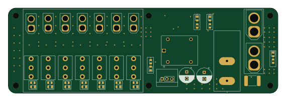
PowerPCB (switches for enabling individual ultrasonic motors, +24V in connector, master power switch))
MotorJoint_Splitter (mounted on robot arm)
* Motor Joint Splitter V3 (mounted next to each actuator)
Motorreroute (at motor controller. Splits Tekcelo control signal to use ethernet for a pair of encoders, and 3 wire sin/cos/gnd cable for 250V )
Main components on the MRIRobot
MRIRobot bill of materials (BOM)
330 components, 49 distinct parts — part numbers from the project's BOM.
| Qty | Part | Footprint | Refs |
|---|---|---|---|
| 1 | NUCLEO-F446RE | MODULE_NUCLEO-F446RE | U1 |
| 1 | FT231XS | SSOP-20_3.9x8.7mm_P0.635mm | U2 |
| 1 | CMOD_A7_FPGA | CMODA7 | U3 |
| 1 | LM22676MR-5 | TI_SO-PowerPAD-8 | U4 |
| 1 | LM22676MR-ADJ | TI_SO-PowerPAD-8 | U5 |
| 3 | LSF0108 | TSSOP-20_4.4x6.5mm_P0.65mm | U6, U7, U8 |
| 1 | SUD08P06-155L | TO-252-2 | Q1 |
| 7 | CONN_01X05 Conn_01x05 | JST_EH_B5B-EH-A_1x05_P2.50mm_Vertical | J1, J2, J3, J5, J6, J7, J8 |
| 1 | USB_C_RECEPTACLE_USB2.0_16P USB_C_Receptacle_USB2.0_16P | USB_C_Receptacle_GCT_USB4105-xx-A_16P_TopMnt_Horizontal | J4 |
| 1 | Power In | AMASS_XT60-M_1x02_P7.20mm_Vertical | J9 |
| 7 | Homing | JST_EH_B2B-EH-A_1x02_P2.50mm_Vertical | J10, J11, J12, J13, J14, J15, J16 |
| 7 | CONN_01X08 Conn_01x08 | JST_EH_B8B-EH-A_1x08_P2.50mm_Vertical | J17, J18, J19, J20, J21, J24, J27 |
| 4 | CONN_01X03 Conn_01x03 | JST_XA_B03B-XASK-1-A_1x03_P2.50mm_Vertical | J22, J23, J25, J26 |
| 1 | RJ45_RB1-125B8G1A RJCSE538001 | AMPHENOL_RJCSE538001 | J28 |
| 3 | RJCSE538001 | AMPHENOL_RJCSE538001 | J32, J33, J34 |
| 1 | 5V Enable | SW_Slide_SPDT_Straight_CK_OS102011MS2Q | SW1 |
| 1 | 3.3V Enable | SW_Slide_SPDT_Straight_CK_OS102011MS2Q | SW2 |
| 1 | TOGGLE_SWITCH0 Toggle_Switch0 | SW_Slide_SPDT_Straight_CK_OS102011MS2Q | SW3 |
| 1 | TOGGLE_SWITCH1 Toggle_Switch1 | SW_Slide_SPDT_Straight_CK_OS102011MS2Q | SW4 |
| 1 | TOGGLE_SWITCH2 Toggle_Switch2 | SW_Slide_SPDT_Straight_CK_OS102011MS2Q | SW5 |
Show 29 more
| Qty | Part | Footprint | Refs |
|---|---|---|---|
| 1 | TOGGLE_SWITCH3 Toggle_Switch3 | SW_Slide_SPDT_Straight_CK_OS102011MS2Q | SW6 |
| 5 | D | D_SMA_Handsoldering | D1, D2, D3, D4, D5 |
| 10 | LED | LED_0805_2012Metric_Pad1.15x1.40mm_HandSolder | D6, D7, D8, D9, D10, D11, D13, D14 +2 |
| 3 | D | D_SOD-128 | D12, D87, D111 |
| 94 | D_TVS | D_SOD-123F | D15, D16, D17, D18, D19, D20, D21, D22 +86 |
| 1 | D_Zener | D_SMA_Handsoldering | D109 |
| 2 | 8.2UH 8.2uH | L_7.3x7.3_H3.5 | L1, L2 |
| 1 | 0.1U 0.1u | C_0603_1608Metric_Pad1.08x0.95mm_HandSolder | C1 |
| 2 | 22UF 22uF | CP_Radial_D5.0mm_P2.00mm | C2, C3 |
| 2 | 6.8UF 6.8uF | C_0805_2012Metric | C4, C5 |
| 7 | 0.01 uF | C_0805_2012Metric_Pad1.18x1.45mm_HandSolder | C6, C7, C12, C13, C14, C15, C16 |
| 2 | 10NF 10nF | C_0805_2012Metric | C8, C9 |
| 2 | 120UF 120uF | CP_Radial_D6.3mm_P2.50mm | C10, C11 |
| 3 | 0.1UF 0.1uF | C_0805_2012Metric_Pad1.18x1.45mm_HandSolder | C17, C18, C19 |
| 42 | 100 pF | C_0805_2012Metric_Pad1.18x1.45mm_HandSolder | C20, C21, C22, C23, C24, C25, C26, C27 +34 |
| 3 | 200K 200k | C_0805_2012Metric_Pad1.18x1.45mm_HandSolder | R1, R2, R3 |
| 8 | 290 | C_0805_2012Metric_Pad1.18x1.45mm_HandSolder | R4, R5, R68, R69, R70, R71, R74, R75 |
| 1 | 100K | R_0805_2012Metric | R6 |
| 42 | 1k | C_0805_2012Metric_Pad1.18x1.45mm_HandSolder | R7, R8, R9, R10, R11, R12, R15, R16 +34 |
| 2 | 5.1K 5.1k | R_0603_1608Metric_Pad0.98x0.95mm_HandSolder | R13, R14 |
| 2 | 27 | R_0603_1608Metric_Pad0.98x0.95mm_HandSolder | R21, R22 |
| 7 | 10K 10k | C_0805_2012Metric_Pad1.18x1.45mm_HandSolder | R47, R48, R49, R50, R51, R52, R53 |
| 14 | 4K | C_0805_2012Metric_Pad1.18x1.45mm_HandSolder | R54, R55, R60, R61, R64, R65, R66, R67 +6 |
| 2 | 6.2K 6.2k | R_0805_2012Metric | R56, R58 |
| 2 | 1k | R_0805_2012Metric | R57, R59 |
| 1 | 976 | R_0805_2012Metric | R62 |
| 1 | 1.54K 1.54k | R_0805_2012Metric | R63 |
| 2 | 290 | C_0805_2012Metric_Pad1.18x1.45mm_HandSolder | R86, R87 |
| 21 | 10k | C_0805_2012Metric_Pad1.18x1.45mm_HandSolder | R110, R111, R112, R113, R114, R115, R116, R117 +13 |
MRIRobot design files
The KiCad project lives in the biomimetics/MRIRobot_PCB repository on GitHub; these links point at the commit this page was built from.
MRIRobot: common questions
How big is the MRIRobot PCB?
The MRIRobot measures 200 × 99 mm, has 4 copper layers and is 1.6 mm thick.
How many components are on the MRIRobot?
330 components, from 49 distinct parts, with part numbers taken from the project's own BOM. The full bill of materials is listed on this page.
Where can I download the MRIRobot design files?
From the biomimetics/MRIRobot_PCB repository on GitHub, which has the KiCad layout, the schematic and the BOM; the links under Design files point to each one.
Can I use the MRIRobot design in my own project?
The repository has no license, so all rights stay with biomimetics. Use it as a reference, and ask the author before reusing the design.
More boards in MRIRobot_PCB
Power
142 × 45 mm58 parts2LNo license2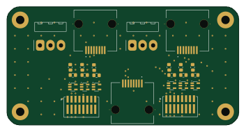
Motor reroute
88 × 45 mm31 parts2LNo license2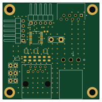
Motor Joint Splitter V3
50 × 50 mm24 parts2LNo license2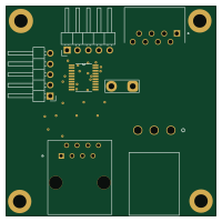
Motor Joint Splitter V3 two side
50 × 50 mm20 parts2LNo license2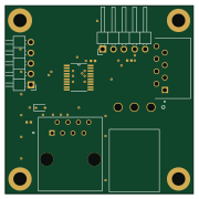
Motor Joint Splitter V3 temp
45 × 45 mm19 parts2LNo license2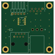
Motor Joint Splitter V2 Set
45 × 45 mm17 parts2LNo license2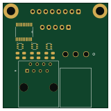
Motor Joint Splitter V2 pre tracks
40 × 40 mm15 parts2LNo license2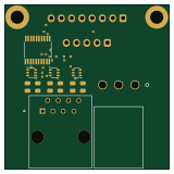
Motor Joint Splitter V2 backup
40 × 40 mm15 parts2LNo license2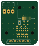
Motor Adapt C
34.5 × 41 mm15 parts2LNo license2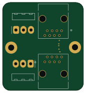
Motor quick connect
42.8 × 46.3 mm4 parts2LNo license2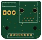
Motor Adapt M
34.5 × 32.5 mm3 parts2LNo license2
Similar boards

Cube batteryboard
willem-pennings
95 × 95 mm4 parts2LGPL-3.01.1k
Rp2040 encoder
Twisted-Fields
36.7 × 33.3 mm10 parts2LCustom license417
VESC Controller
paltatech
160 × 90 mm908 parts2LNo license354
${BOARD NAME} Assembly
EPFLXplore
45 × 43.5 mm21 parts4LApache-2.0345
Volumetric display
idlehandsdev
23 × 120 mm70 parts2LCC-BY-SA-4.0312
OpenESC-20x20
OpenDrone-hw
31.2 × 33 mm180 parts6LCERN-OHL-S-2.0243