
Alarm clock

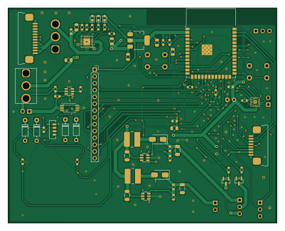
About the Alarm clock PCB
Alarm clock is an open source ESP32 PCB design by Carabouille, published on GitHub. It is a 2-layer board measuring 100 × 80 mm, with 59 components from 40 distinct parts.
Its main chip is the ESP32-S3-WROOM-1, from the ESP32 family. Other key parts include the MCP73871-2AA, AMS1117-3.3, DW01A, FS8205A and MAX98357A. By type, the board carries 20 resistors, 17 capacitors, 9 ICs, 6 diodes, 3 connectors and 2 transistors.
It belongs with the audio, power & battery and sensors designs in this gallery.
From the project
A description of my Alarm clock with dawn simulator for the Fallout event organised By Hackclub
AND see just how beautiful it is !!! Yeah I know I did a great job you can tell me ^^
And to see how it works in details you can watch the video that I did on my alarm clock : (CLICK ON MY AWESOME FACE !)
I really can't wait to build my project, develop my skills and learn so much! I'm gonna give the best version of myself to be proud of my alarm clocks and I also hope that I will have the chance to go to Shenzen to meet other hardware fans! Kind regards, your French friend, Florian "Carabouille" CHARLES :))

Main components on the Alarm clock
Alarm clock bill of materials (BOM)
59 components, 40 distinct parts — part numbers from the project's BOM.
| Qty | Part | Footprint | Refs |
|---|---|---|---|
| 1 | MCP73871-2AA | QFN-20-1EP_4x4mm_P0.5mm_EP2.5x2.5mm | U1 |
| 1 | AMS1117-3.3 | SOT-223-3_TabPin2 | U2 |
| 1 | DW01A | SOT-23-6 | U3 |
| 1 | FS8205A | TSSOP-8_4.4x3mm_P0.65mm | U4 |
| 1 | ESP32-S3-WROOM-1 | ESP32-S3-WROOM-1 | U5 |
| 1 | MAX98357A | TQFN-16-1EP_3x3mm_P0.5mm_EP1.23x1.23mm | U6 |
| 1 | MT3608 | SOT-23-6 | U7 |
| 1 | C84817 MT3608 | SOT-23-6 | U8 |
| 1 | VEML770 | XDCR_VEML7700-TR | U10 |
| 1 | AO3400A | SOT-23 | Q1 |
| 1 | C20917 AO3400A | SOT-23 | Q2 |
| 1 | CONN_01X12_PIN Conn_01x12_Pin | JUSHUO_AFA07-S12FCA-00_1x12-1MP_P1.0mm_Horizontal | J1 |
| 2 | C262714 Conn_01x08_Pin | JUSHUO_AFA07-S08FCA-00_1x8-1MP_P1.0mm_Horizontal | J8, J11 |
| 3 | LED | LED_0603_1608Metric | D1, D2, D3 |
| 1 | SS14 | D_SMA | D4 |
| 1 | C2837270 SS14 | D_SMA | D5 |
| 1 | 1N4148 | D_DO-35_SOD27_P7.62mm_Horizontal | D15 |
| 1 | 22u | IND_CD54_SUM | L1 |
| 1 | C2826664 22u | IND_CD54_SUM | L2 |
| 2 | 10u | C_0805_2012Metric | C1, C4 |
Show 20 more
| Qty | Part | Footprint | Refs |
|---|---|---|---|
| 1 | 4.7u | C_0805_2012Metric | C2 |
| 1 | C98192 4.7u | C_0805_2012Metric | C3 |
| 1 | 22u | C_0805_2012Metric | C5 |
| 4 | 0.1u | C_0603_1608Metric | C6, C7, C9, C37 |
| 1 | 1u | C_0805_2012Metric | C8 |
| 3 | 22u | C_1206_3216Metric | C11, C13, C14 |
| 1 | C14 22u | C_1206_3216Metric | C12 |
| 1 | C_0805_2012METRIC 10u | C_0805_2012Metric | C15 |
| 1 | C21 0.1u | C_0603_1608Metric | C16 |
| 1 | C6 0.1u | C_0603_1608Metric | C17 |
| 8 | 10k | R_0603_1608Metric | R3, R5, R11, R15, R16, R18, R19, R21 |
| 4 | 1k | R_0603_1608Metric | R4, R7, R8, R9 |
| 1 | R8 1k | R_0603_1608Metric | R6 |
| 1 | 100 | R_0603_1608Metric | R10 |
| 1 | 1000K 1000k | R_0603_1608Metric | R12 |
| 1 | 390K 390k | R_0603_1608Metric | R13 |
| 1 | R16 10k | R_0603_1608Metric | R14 |
| 1 | 180K 180k | R_0603_1608Metric | R17 |
| 1 | 2.2k | R_0603_1608Metric | R22 |
| 1 | C114662 2.2k | R_0603_1608Metric | R23 |
Alarm clock design files
The KiCad project lives in the Carabouille/Alarm_Clock_dawn_simulator repository on GitHub; these links point at the commit this page was built from.
Alarm clock: common questions
What microcontroller does the Alarm clock use?
The Alarm clock is built around the ESP32-S3-WROOM-1, from the ESP32 family.
How big is the Alarm clock PCB?
The Alarm clock measures 100 × 80 mm, has 2 copper layers and is 1.6 mm thick.
How many components are on the Alarm clock?
59 components, from 40 distinct parts, with part numbers taken from the project's own BOM. The full bill of materials is listed on this page.
Where can I download the Alarm clock design files?
From the Carabouille/Alarm_Clock_dawn_simulator repository on GitHub, which has the KiCad layout, the schematic and the BOM; the links under Design files point to each one.
Can I use the Alarm clock design in my own project?
The repository has no license, so all rights stay with Carabouille. Use it as a reference, and ask the author before reusing the design.
Can I test firmware for the Alarm clock without the hardware?
Yes. HardLabs builds a simulation of the board from its netlist and BOM, so you can run and debug ESP32 firmware against it before you order a PCB.
More boards in Alarm_Clock_dawn_simulator
Similar boards
 ESP32
ESP32Open Book Abridged Edition
joeycastillo
85 × 115 mm65 parts2LCC-BY-SA-4.08.1k ESP32
ESP32Badge
atopile
56.3 × 39 mm239 parts4LMIT4.0k ESP32
ESP32Esp32 minimal
36.2 × 26.8 mm20 parts2LMIT4.0k ESP32
ESP32Racer
StuckAtPrototype
36 × 50.2 mm70 parts4LApache-2.03.8k ESP32
ESP32Controller
29 × 74 mm58 parts4LApache-2.03.8k ESP32
ESP32Bitaxe
skot
56.5 × 99.8 mm86 parts4LCERN-OHL-S-2.01.4k