
Mie1001 daq board

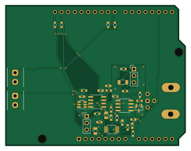
About the Mie1001 daq board
Mie1001 daq board is an open source AVR/Arduino PCB design by Chaospossum, published on GitHub. It is a 2-layer board measuring 68.6 × 53.3 mm, with 38 components from 22 distinct parts.
Its main chip is the A000066, from the AVR/Arduino family. Other key parts include the MCP4725A0T-E/CH, ADS1115IDGSR, MCP6002-I/SN and LMP7721MA/NOPB. By type, the board carries 17 resistors, 10 capacitors, 4 ICs, 4 connectors, 1 module and 1 jumper.
It belongs with the dev boards & breakouts designs in this gallery.
From the project
MIE1001 Team 5: DAQ firmware and Arduino shield designs (preamp, ADS1115, MCP4725)
Data-acquisition shield for the portable quadrupole mass spectrometer. It measures the detector current (pA to µA) with an electrometer transimpedance amplifier and a 16-bit ADC, and drives the QPS mass command with a 12-bit DAC. It plugs onto an Arduino UNO R3 and takes all power from the UNO's 5 V rail.
Both files are generated. Edit the Python, then run ./build.sh. Editing the .kicadsch/.kicadpcb in the GUI works, but the next ./build.sh overwrites it.
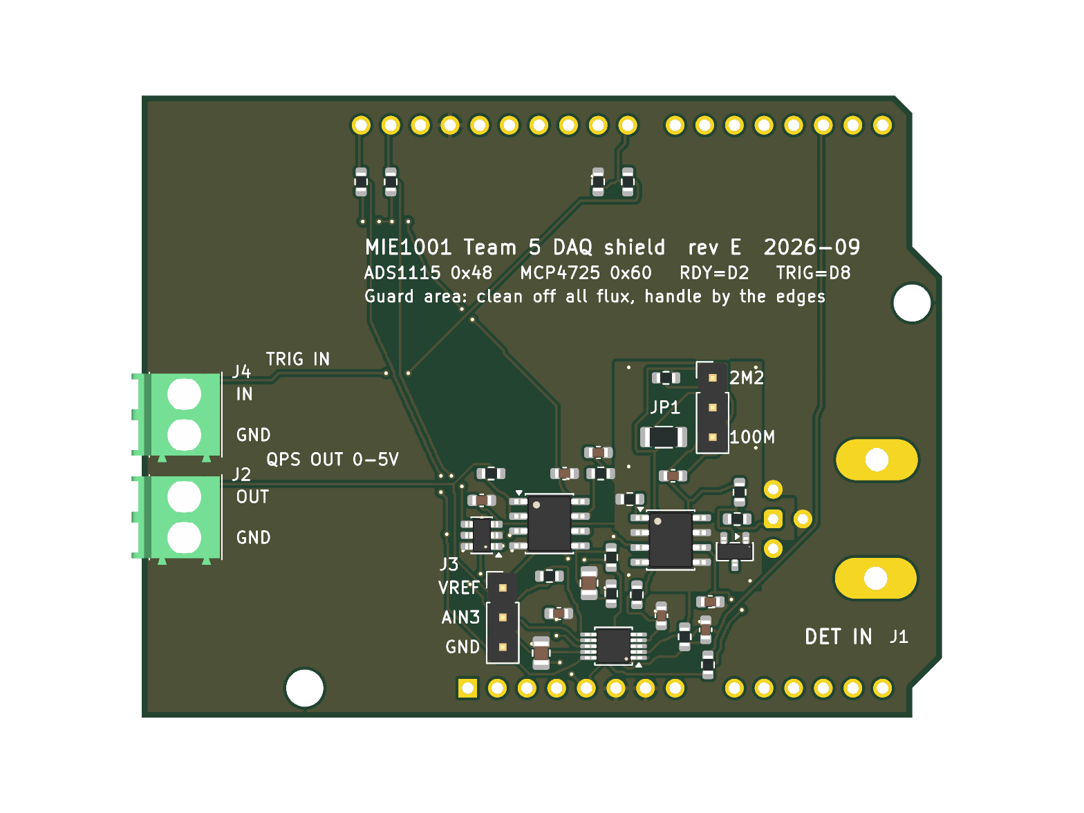
Main components on the Mie1001 daq board
Mie1001 daq board bill of materials (BOM)
38 components, 22 distinct parts — part numbers from the project's BOM.
| Qty | Part | Footprint | Refs |
|---|---|---|---|
| 1 | MCP4725A0T-E/CH Microchip | SOT-23-6 | U1 |
| 1 | ADS1115IDGSR Texas Instruments | MSOP-10_3x3mm_P0.5mm | U2 |
| 1 | MCP6002-I/SN Microchip | SOIC-8_3.9x4.9mm_P1.27mm | U3 |
| 1 | LMP7721MA/NOPB Texas Instruments | SOIC-8_3.9x4.9mm_P1.27mm | U4 |
| 1 | A000066 Arduino UNO R3 Arduino | Arduino_UNO_R3 | A1 |
| 1 | 031-6575 Detector in Amphenol RF | BNC_Amphenol_031-6575_Horizontal | J1 |
| 1 | 1984617 QPS cmd out Phoenix Contact | TerminalBlock_Phoenix_PT-1,5-2-3.5-H_1x02_P3.50mm_Horizontal | J2 |
| 1 | PRPC040SAAN-RC VREF/AIN3 Sullins | PinHeader_1x03_P2.54mm_Vertical | J3 |
| 1 | 1984617 Trigger in Phoenix Contact | TerminalBlock_Phoenix_PT-1,5-2-3.5-H_1x02_P3.50mm_Horizontal | J4 |
| 1 | PRPC040SAAN-RC Range select Sullins | PinHeader_1x03_P2.54mm_Vertical | JP1 |
| 1 | BAV199LT1G onsemi | SOT-23 | D1 |
| 1 | GRM1885C1H100JA01D 10pF Murata | C_0603_1608Metric | C1 |
| 3 | CL10A105KB8NNNC 1uF Samsung | C_0603_1608Metric | C2, C9, C10 |
| 2 | CL21A106KAYNNNE 10uF Samsung | C_0805_2012Metric | C3, C7 |
| 4 | CL10B104KB8NNNC 100nF Samsung | C_0603_1608Metric | C4, C5, C6, C8 |
| 1 | RC0603FR-072M2L 2M2 Yageo | R_0603_1608Metric | R1 |
| 1 | HVCB1206FKC100M 100M Stackpole | R_1206_3216Metric | R2 |
| 6 | RC0603FR-071KL 1k Yageo | R_0603_1608Metric | R3, R4, R9, R13, R16, R17 |
| 2 | RC0603FR-074K7L 4k7 Yageo | R_0603_1608Metric | R5, R6 |
| 4 | RC0603FR-0710KL 10k Yageo | R_0603_1608Metric | R7, R8, R10, R11 |
Show 2 more
| Qty | Part | Footprint | Refs |
|---|---|---|---|
| 2 | RC0603FR-07100RL 100R Yageo | R_0603_1608Metric | R12, R15 |
| 1 | ERJ-PA3F1002V 10k Panasonic | R_0603_1608Metric | R14 |
Mie1001 daq board design files
The KiCad project lives in the Chaospossum/mie1001-daq repository on GitHub; these links point at the commit this page was built from.
Mie1001 daq board: common questions
What microcontroller does the Mie1001 daq board use?
The Mie1001 daq board is built around the A000066, from the AVR/Arduino family.
How big is the Mie1001 daq board?
The Mie1001 daq board measures 68.6 × 53.3 mm, has 2 copper layers and is 1.6 mm thick.
How many components are on the Mie1001 daq board?
38 components, from 22 distinct parts, with part numbers taken from the project's own BOM. The full bill of materials is listed on this page.
Where can I download the Mie1001 daq board design files?
From the Chaospossum/mie1001-daq repository on GitHub, which has the KiCad layout, the schematic and the BOM; the links under Design files point to each one.
Can I use the Mie1001 daq board design in my own project?
The repository has no license, so all rights stay with Chaospossum. Use it as a reference, and ask the author before reusing the design.
Can I test firmware for the Mie1001 daq board without the hardware?
Yes. HardLabs builds a simulation of the board from its netlist and BOM, so you can run and debug AVR/Arduino firmware against it before you order a PCB.
More boards in mie1001-daq
Similar boards
 AVR/Arduino
Redox keyboard
mattdibi
162.2 × 126.5 mm77 parts2LMIT2.0k AVR/Arduino
ModuleV450
stuartpittaway
30 × 61.4 mm39 parts2LCC-BY-NC-4.01.1k AVR/Arduino
V4
30 × 50 mm38 parts2LCC-BY-NC-4.01.1k AVR/Arduino
Discipline
coseyfannitutti
304.9 × 122.8 mm170 parts2LCC-BY-NC-4.01.0k AVR/Arduino
Megadesk
gcormier
41.7 × 32.2 mm23 parts2LGPL-3.0818 AVR/Arduino
Easyduino Atmega Nano
Hanqaqa
43.4 × 18 mm30 parts4LCERN-OHL-P-2.0746