
Qcomlt debugboard

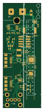
About the Qcomlt debugboard PCB
Qcomlt debugboard is an open source Microchip SAM PCB design by CodeLinaro-mirror, published on GitHub under the CERN-OHL-P-2.0 license. It is a 4-layer board measuring 20 × 55.7 mm, with 38 components from 25 distinct parts.
Its main chip is the ATSAMD11D14A-MUT, from the Microchip SAM family. Other key parts include the TXS0104ERGYR, TPS79318DBVR, USBLC6-2P6, TPS79333DBVR and INA233AIDGST. By type, the board carries 13 capacitors, 10 resistors, 8 ICs, 6 connectors and 1 inductor.
From the project
96boards specifications compliant Mezzanine used to control the DC Input, USB VBUS, PWR/RST buttons and Debug UART via a single USB2.0 CDC interface.
96boards specifications compliant Mezzanine used to control the DC Input, USB VBUS, PWR/RST buttons and Debug UART via a single USB2.0 CDC interface.
The current design has been saved from KiCad 7.
Firmware is available at linaro/qcomlt/debugboard-fw, Gerber zip file in gerber/ directory and assembly files (BOM and positions) in assembly/ directory.
CERN-OHL-P (CERN Open Hardware Licence v2 permissive)
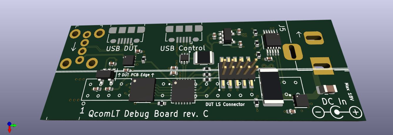
Main components on the Qcomlt debugboard
Qcomlt debugboard bill of materials (BOM)
38 components, 25 distinct parts — part numbers from the project's BOM.
| Qty | Part | Footprint | Refs |
|---|---|---|---|
| 1 | TXS0104ERGYR Texas Instruments | Texas_S-PVQFN-N14 | IC1 |
| 1 | TPS79318DBVR Texas Instruments | SOT-23-5 | U1 |
| 1 | USBLC6-2P6 STMicroelectronics | SOT-666 | U2 |
| 1 | TPS79333DBVR Texas Instruments | SOT-23-5 | U3 |
| 1 | ATSAMD11D14A-MUT ATSAMD11D14A-M Microchip Tech | QFN-24-1EP_4x4mm_P0.5mm_EP2.6x2.6mm | U4 |
| 1 | INA233AIDGST INA233 Texas Instruments | VSSOP-10_3x3mm_P0.5mm | U5 |
| 2 | TPS22810DRVR TPS22810DRV Texas Instruments | WSON-6-1EP_2x2mm_P0.65mm_EP1x1.6mm | U7, U8 |
| 2 | 10118194-0001LF Micro-USB Amphenol ICC | USB_Micro-B_Amphenol_10118194_Horizontal | J1, J4 |
| 1 | 57202-G52-20LF LS1 Amphenol ICC | PinHeader_2x20_P2.00mm_Vertical_SMD_Mirrored | J2 |
| 1 | 4048 SWD Adafruit | PinHeader_2x05_P1.27mm_Vertical_SMD | J3 |
| 1 | C16214 Barrel_Jack_Switch BOOMELE(Boom Precision Elec) | BarrelJack_Horizontal | J5 |
| 1 | 73725-0110BLF Amphenol FCI | USB_A_Female_Vertical_RA_73725-0110BLF | J7 |
| 1 | CBG322513U102T 100@100MHz FH (Guangdong Fenghua Advanced Tech) | R_1210_3225Metric | FB1 |
| 3 | CL05B104KO5NNNC 0.1uF Samsung Electro-Mechanicsn | C_0402_1005Metric | C1, C4, C7 |
| 2 | CL05B103KB5NNNC 0.01uF Samsung Electro-Mechanics | C_0402_1005Metric | C2, C5 |
| 2 | CL05A106MQ5NUNC 10uF Samsung Electro-Mechanics | C_0402_1005Metric | C3, C6 |
| 1 | CL05A475MP5NRNC 4.7uF Samsung Electro-Mechanics | C_0402_1005Metric | C8 |
| 1 | CL05B104KO5NNNC 100nF Samsung Electro-Mechanics | C_0402_1005Metric | C9 |
| 1 | CL05A105KA5NQNC 1uF Samsung Electro-Mechanics | C_0402_1005Metric | C10 |
| 2 | CL05B103KB5NNNC 10nF Samsung Electro-Mechanics | C_0402_1005Metric | C11, C13 |
Show 5 more
| Qty | Part | Footprint | Refs |
|---|---|---|---|
| 1 | CL21B105KBFNNNE 1uF Samsung Electro-Mechanics | C_0805_2012Metric | C12 |
| 1 | 0402WGF1001TCE 1k UNI-ROYAL(Uniroyal Elec) | R_0402_1005Metric | R1 |
| 1 | 25121WF200MT4E 0.02 UNI-ROYAL(Uniroyal Elec) | R_2512_6332Metric | R5 |
| 3 | 0402WGF220JTCE 22 UNI-ROYAL(Uniroyal Elec) | R_0402_1005Metric | R6, R9, R11 |
| 5 | 0402WGF4701TCE 4k7 UNI-ROYAL(Uniroyal Elec) | R_0402_1005Metric | R7, R8, R10, R12, R13 |
Qcomlt debugboard design files
The KiCad project lives in the CodeLinaro-mirror/qcomlt_debugboard repository on GitHub; these links point at the commit this page was built from.
Qcomlt debugboard: common questions
What microcontroller does the Qcomlt debugboard use?
The Qcomlt debugboard is built around the ATSAMD11D14A-MUT, from the Microchip SAM family.
How big is the Qcomlt debugboard PCB?
The Qcomlt debugboard measures 20 × 55.7 mm, has 4 copper layers and is 1.6 mm thick.
How many components are on the Qcomlt debugboard?
38 components, from 25 distinct parts, with part numbers taken from the project's own BOM. The full bill of materials is listed on this page.
Where can I download the Qcomlt debugboard design files?
From the CodeLinaro-mirror/qcomlt_debugboard repository on GitHub, which has the KiCad layout, the schematic and the BOM; the links under Design files point to each one.
Can I use the Qcomlt debugboard design in my own project?
Yes, under the terms of its CERN-OHL-P-2.0 license, which CodeLinaro-mirror chose for the repository.
Can I test firmware for the Qcomlt debugboard without the hardware?
Yes. HardLabs builds a simulation of the board from its netlist and BOM, so you can run and debug Microchip SAM firmware against it before you order a PCB.
Similar boards
 Microchip SAM
Microcontroller Expansion Card
FrameworkComputer
26 × 30 mm24 parts2LCC-BY-4.01.1k Microchip SAM
Taco Raven
VoronDesign
120 × 113 mm349 parts4LGPL-3.01.1k Microchip SAM
Fpgaboy
Wren6991
50 × 50 mm89 parts4LNo license511 Microchip SAM
OpenDropV4
GaudiLabs
124 × 115.4 mm118 parts2LGPL-3.0487 Microchip SAM
ModulAdapter universal
100 × 69.5 mm45 parts2LGPL-3.0487 Microchip SAM
Kira
kiibohd
366.9 × 114.3 mm400 partsCERN-OHL-1.2416