
SPINC

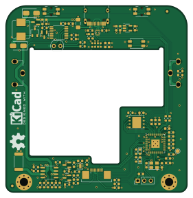
About the SPINC PCB
SPINC is an open source RP2040/RP2350 PCB design by CoretechR, published on GitHub under the GPL-3.0 license. It is a 4-layer board measuring 70 × 72 mm, with 91 components from 44 distinct parts.
Its main chip is the RP2040, from the RP2040/RP2350 family. Other key parts include the LM27761, USBLC6-2P6, W25Q64JVZPIQ, AP2112K-3.3 and VCNL4040M3OE. By type, the board carries 32 resistors, 29 capacitors, 7 ICs, 5 transistors, 5 connectors and 5 diodes.
It belongs with the power & battery and displays & leds designs in this gallery.
From the project
DIY Automatic Battery Charger Using RP2040
SPINC is an Open-Source NiMH charging station that can automatically load and eject AA battery cells. Simply drop batteries into the top of the device, regardless of their polarity. The internal mechanism picks up one cell at a time and fast-charges them sequentially. Up to 7 fully charged batteries can be conveniently stored inside the device for easy access. In addition, SPINC doubles as a desk clock, displaying the date and time on its high-resolution LCD.
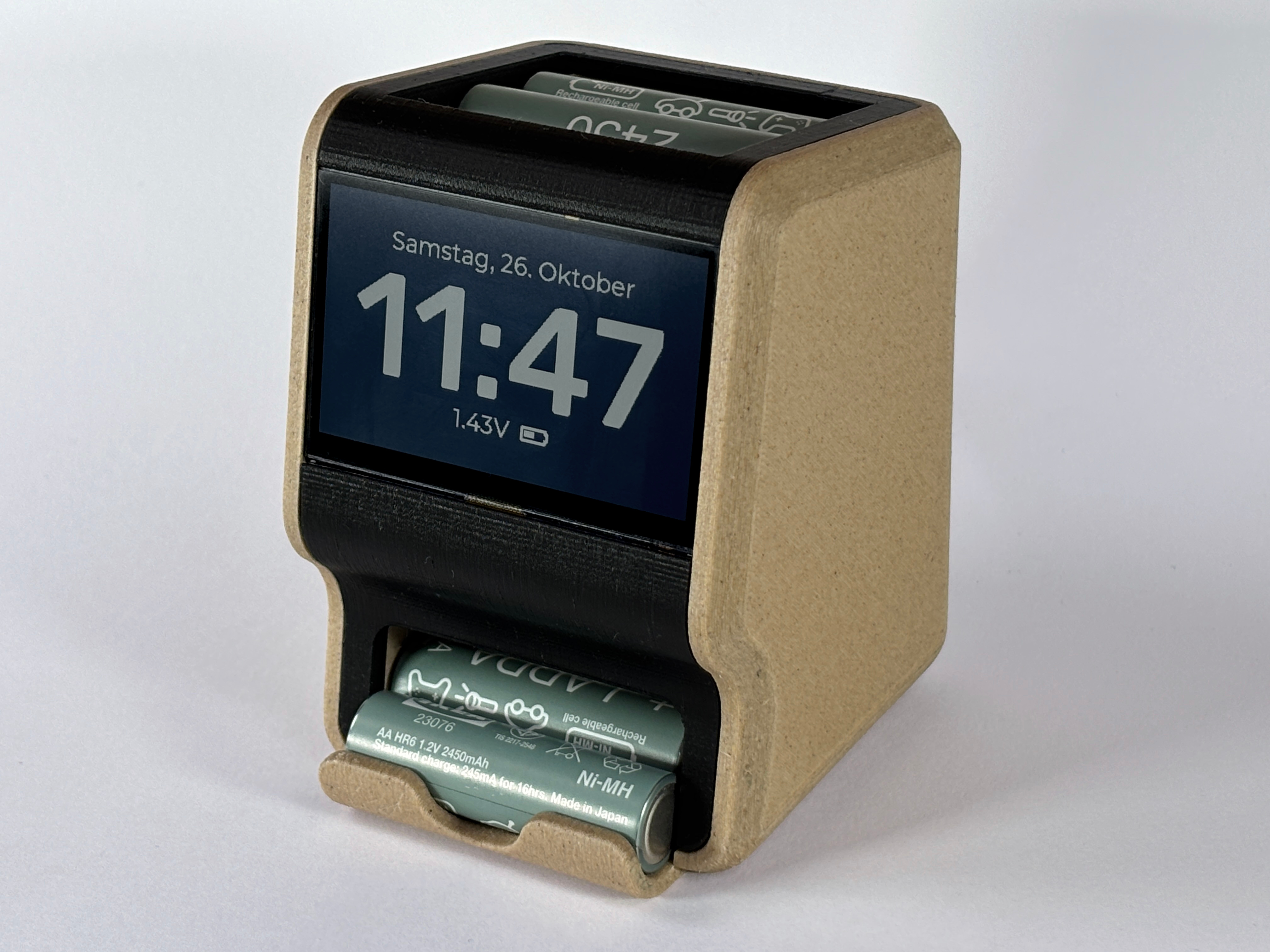
Main components on the SPINC
SPINC bill of materials (BOM)
91 components, 44 distinct parts — part numbers from the project's BOM.
| Qty | Part | Footprint | Refs |
|---|---|---|---|
| 1 | LM27761 | WSON-8-1EP_2x2mm_P0.5mm_EP0.9x1.6mm | U1 |
| 1 | USBLC6-2P6 | SOT-666 | U2 |
| 1 | W25Q64JVZPIQ | WSON-8-1EP_6x5mm_P1.27mm_EP3.4x4.3mm | U3 |
| 1 | AP2112K-3.3 | SOT-23-5 | U4 |
| 1 | RP2040 | QFN-56-1EP_7x7mm_P0.4mm_EP3.2x3.2mm | U5 |
| 1 | VCNL4040M3OE | VISHAY_VCNL4040_4X2X1.1 | U7 |
| 1 | DS2712 | TSSOP-16_4.4x5mm_P0.65mm | U8 |
| 3 | DMG2301L | SOT-23 | Q1, Q3, Q4 |
| 1 | DMHC3025LSD | SO-8_3.9x4.9mm_P1.27mm | Q2 |
| 1 | SI2305CDS | SOT-23 | Q5 |
| 1 | ABM8-272-T3 | Crystal_SMD_Abracon_ABM8G-4Pin_3.2x2.5mm | Y1 |
| 1 | USB_C_RECEPTACLE_USB2.0 USB_C_Receptacle_USB2.0 | USB_C_Receptacle_HRO_TYPE-C-31-M-12 | J1 |
| 1 | CONN_01X03_PIN Conn_01x03_Pin | PinHeader_1x03_P2.54mm_Vertical | J2 |
| 1 | CONN_01X10_SOCKET Conn_01x10_Socket | 68711014022 | J3 |
| 2 | CONN_01X01_PIN Conn_01x01_Pin | BatteryHolder_Keystone_590 | J4, J5 |
| 1 | C151162 1A | Fuse_1206_3216Metric_Pad1.42x1.75mm_HandSolder | F1 |
| 2 | SW_Push | Panasonic_EVQPUM_EVQPUD | SW1, SW3 |
| 1 | SW_Push | SW_SPST_EVQP2 | SW2 |
| 2 | C13564 Thermistor_NTC | R_0603_1608Metric | TH1, TH2 |
| 2 | LED | LED_0603_1608Metric | D1, D5 |
Show 24 more
| Qty | Part | Footprint | Refs |
|---|---|---|---|
| 2 | MBRA340 | D_SMA | D2, D4 |
| 1 | MMBD4148 | TSOT-23 | D3 |
| 1 | SRP7050TA-470M | L_Bourns_SRP7050TA_7.3x6.6mm | L1 |
| 2 | 4.7UF 4.7uF | C_0603_1608Metric | C1, C3 |
| 9 | 1UF 1uF | C_0603_1608Metric | C2, C4, C6, C8, C9, C15, C17, C20 +1 |
| 3 | 2.2UF 2.2uF | C_0603_1608Metric | C5, C7, C25 |
| 12 | 100NF 100nF | C_0603_1608Metric | C10, C13, C14, C16, C18, C19, C21, C22 +4 |
| 2 | 15PF 15pF | C_0603_1608Metric | C11, C12 |
| 1 | 10UF 10uF | C_0603_1608Metric | C30 |
| 1 | 1k | R_0603_1608Metric | R2 |
| 2 | 5.1K 5.1k | R_0603_1608Metric | R3, R4 |
| 2 | 100K 100k | R_0603_1608Metric | R5, R33 |
| 1 | 57.6K 57.6k | R_0603_1608Metric | R6 |
| 2 | 27 | R_0603_1608Metric | R7, R8 |
| 10 | 10K 10k | R_0603_1608Metric | R9, R15, R16, R19, R24, R25, R26, R27 +2 |
| 2 | 2K2 2k2 | R_0603_1608Metric | R10, R14 |
| 2 | 4K7 4k7 | R_0603_1608Metric | R18, R23 |
| 1 | 0 | R_0603_1608Metric | R20 |
| 4 | 47K 47k | R_0603_1608Metric | R21, R22, R28, R29 |
| 1 | 100 | R_0603_1608Metric | R30 |
| 1 | 22K 22k | R_0603_1608Metric | R32 |
| 1 | 0R124 | R_2512_6332Metric | R34 |
| 1 | 10 | R_0603_1608Metric | R35 |
| 1 | 330 | R_0603_1608Metric | R37 |
SPINC design files
The KiCad project lives in the CoretechR/SPINC repository on GitHub; these links point at the commit this page was built from.
SPINC: common questions
What microcontroller does the SPINC use?
The SPINC is built around the RP2040, from the RP2040/RP2350 family.
How big is the SPINC PCB?
The SPINC measures 70 × 72 mm, has 4 copper layers and is 1.565 mm thick.
How many components are on the SPINC?
91 components, from 44 distinct parts, with part numbers taken from the project's own BOM. The full bill of materials is listed on this page.
Where can I download the SPINC design files?
From the CoretechR/SPINC repository on GitHub, which has the KiCad layout, the schematic and the BOM; the links under Design files point to each one.
Can I use the SPINC design in my own project?
Yes, under the terms of its GPL-3.0 license, which CoretechR chose for the repository.
Can I test firmware for the SPINC without the hardware?
Yes. HardLabs builds a simulation of the board from its netlist and BOM, so you can run and debug RP2040/RP2350 firmware against it before you order a PCB.
Similar boards
 RP2040/RP2350
Open Book Abridged Edition
joeycastillo
85 × 115 mm29 parts2LCC-BY-SA-4.08.1k RP2040/RP2350
Corne
foostan
277.2 × 107.5 mm164 parts2LCC-BY-4.07.7k RP2040/RP2350
Corne
277.2 × 107.5 mm164 parts2LCC-BY-4.07.7k RP2040/RP2350
Jitx design
gusmanb
55.5 × 65 mm26 parts4LGPL-3.05.0k RP2040/RP2350
LogicAnalyzer
57 × 55.2 mm6 parts2LGPL-3.05.0k RP2040/RP2350
Main
google
98 × 71 mm102 parts2LApache-2.02.9k