
DCC-Booster

About the DCC-Booster PCB
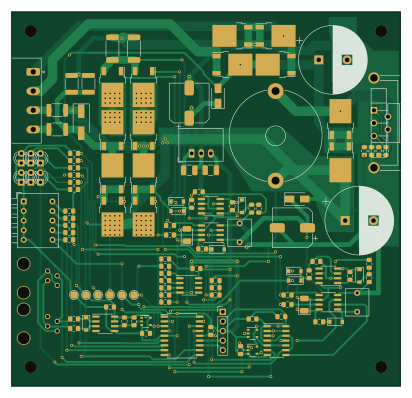
DCC-Booster is an open source PIC PCB design by DavidMFlynn, published on GitHub under the GPL-3.0 license. It is a 2-layer board measuring 102.9 × 99.1 mm, with 118 components from 48 distinct parts.
Its main chip is the PIC16F1847-IP, from the PIC family. Other key parts include the MC34167, R-78E5.0-1.0, 74HC08, IR2101 and 74AHC1G04. By type, the board carries 40 resistors, 27 diodes, 26 capacitors, 13 ICs, 4 transistors and 3 inductors.
From the project
DCC Booster
Main components on the DCC-Booster
DCC-Booster bill of materials (BOM)
118 components, 48 distinct parts.
| Qty | Part | Footprint | Refs |
|---|---|---|---|
| 1 | MC34167 | TO-220-5_P3.4x3.7mm_StaggerOdd_Lead3.8mm_Vertical | U1 |
| 1 | R-78E5.0-1.0 | Converter_DCDC_RECOM_R-78E-0.5_THT | U2 |
| 1 | 74HC08 | SOIC-14_3.9x8.7mm_P1.27mm | U3 |
| 2 | IR2101 | SOIC-8_3.9x4.9mm_P1.27mm | U4, U5 |
| 2 | 74AHC1G04 | TSOP-5_1.65x3.05mm_P0.95mm | U6, U11 |
| 1 | 6N137 | SOIC-8_3.9x4.9mm_P1.27mm | U7 |
| 1 | PIC16F1847-IP | SOIC-18W_7.5x11.6mm_P1.27mm | U8 |
| 1 | 74AHC1G86 | TSOP-5_1.65x3.05mm_P0.95mm | U9 |
| 1 | LM358 | SOIC-8_3.9x4.9mm_P1.27mm | U10 |
| 2 | LM555CM | SOIC-8_3.9x4.9mm_P1.27mm | U12, U13 |
| 4 | Q_NMOS_GDS | TO-252-2 | Q1, Q2, Q3, Q4 |
| 1 | Conn_01x04 | PhoenixContact_MSTBA_2,5_4-G-5,08_1x04_P5.08mm_Horizontal | J1 |
| 1 | Prog | PinHeader_1x05_P2.54mm_Vertical | J4 |
| 1 | Heatsink_Fischer_FK224xx2201_25x8.3mm | Heatsink_Fischer_FK224xx2201_25x8.3mm | HS1 |
| 1 | SW_DIP_x05 | SW_DIP_SPSTx05_Piano_10.8x14.26mm_W7.62mm_P2.54mm | SW1 |
| 1 | 20V 1500W | D_SMA-SMB_Universal_Handsoldering | TVS1 |
| 10 | SBR545D1 | TO-252-2 | D1, D2, D3, D4, D6, D7, D10, D11 +2 |
| 2 | MRA4003T3G | D_SMA | D5, D27 |
| 2 | B140-E3 | D_SOD-123 | D8, D9 |
| 1 | 1N4148 | D_SOD-123 | D14 |
Show 28 more
| Qty | Part | Footprint | Refs |
|---|---|---|---|
| 6 | LED_ALT | LED_D3.0mm | D15, D16, D17, D18, D19, D20 |
| 4 | 1N4148W | D_SOD-123 | D21, D22, D23, D24 |
| 2 | BZT52C15 | D_SOD-123 | D25, D26 |
| 2 | Ferrite_Bead | L_1812_4532Metric_Pad1.30x3.40mm_HandSolder | FB1, FB2 |
| 1 | 180uH 6A | L_Radial_D24.4mm_P23.70mm_muRATA_1400series | L1 |
| 14 | 0.1uf50v | C_0805_2012Metric_Pad1.15x1.40mm_HandSolder | C1, C5, C7, C12, C13, C14, C15, C16 +6 |
| 1 | 10uf50v | C_1210_3225Metric_Pad1.42x2.65mm_HandSolder | C2 |
| 1 | 22uf10v | C_1210_3225Metric_Pad1.42x2.65mm_HandSolder | C3 |
| 1 | 330uF | CP_Radial_D18.0mm_P7.50mm | C4 |
| 1 | 4700uF25v | CP_Radial_D18.0mm_P7.50mm | C6 |
| 2 | 1uf Poly | C_Rect_L7.0mm_W6.0mm_P5.00mm | C8, C9 |
| 2 | 6.8uf Tant | CP_EIA-3528-21_Kemet-B_Pad1.50x2.35mm_HandSolder | C10, C11 |
| 2 | 220uF | CP_Elec_10x10 | C23, C24 |
| 2 | 0.01uf50v | C_0805_2012Metric_Pad1.15x1.40mm_HandSolder | C25, C26 |
| 1 | 68K | R_0805_2012Metric_Pad1.15x1.40mm_HandSolder | R1 |
| 1 | 3K3 | R_0805_2012Metric_Pad1.15x1.40mm_HandSolder | R2 |
| 2 | 6K8 | R_0805_2012Metric_Pad1.15x1.40mm_HandSolder | R3, R17 |
| 6 | 10R | R_0805_2012Metric_Pad1.15x1.40mm_HandSolder | R4, R5, R6, R7, R39, R40 |
| 8 | 10K | R_0805_2012Metric_Pad1.15x1.40mm_HandSolder | R8, R14, R16, R29, R30, R33, R35, R36 |
| 6 | 1K0 | R_0805_2012Metric_Pad1.15x1.40mm_HandSolder | R9, R18, R19, R20, R21, R31 |
| 2 | 470 | R_0805_2012Metric_Pad1.15x1.40mm_HandSolder | R10, R11 |
| 2 | 4K7 0.5W | R_1812_4532Metric_Pad1.30x3.40mm_HandSolder | R12, R13 |
| 2 | 0R10 3W | R_2512_6332Metric_Pad1.52x3.35mm_HandSolder | R15, R34 |
| 1 | 15K | R_0805_2012Metric_Pad1.15x1.40mm_HandSolder | R22 |
| 1 | 4K7 | R_0805_2012Metric_Pad1.15x1.40mm_HandSolder | R23 |
| 5 | 47K | R_0805_2012Metric_Pad1.15x1.40mm_HandSolder | R24, R25, R26, R27, R28 |
| 1 | 100K | R_0805_2012Metric_Pad1.15x1.40mm_HandSolder | R32 |
| 2 | 100 | R_0805_2012Metric_Pad1.15x1.40mm_HandSolder | R37, R38 |
DCC-Booster design files
The KiCad project lives in the DavidMFlynn/DCC-Booster repository on GitHub; these links point at the commit this page was built from.
DCC-Booster: common questions
What microcontroller does the DCC-Booster use?
The DCC-Booster is built around the PIC16F1847-IP, from the PIC family.
How big is the DCC-Booster PCB?
The DCC-Booster measures 102.9 × 99.1 mm, has 2 copper layers and is 1.6 mm thick.
How many components are on the DCC-Booster?
118 components, from 48 distinct parts. The full bill of materials is listed on this page.
Where can I download the DCC-Booster design files?
From the DavidMFlynn/DCC-Booster repository on GitHub, which has the KiCad layout; the links under Design files point to each one.
Can I use the DCC-Booster design in my own project?
Yes, under the terms of its GPL-3.0 license, which DavidMFlynn chose for the repository.
Can I test firmware for the DCC-Booster without the hardware?
Yes. HardLabs builds a simulation of the board from its netlist and BOM, so you can run and debug PIC firmware against it before you order a PCB.
Similar boards
 PIC
PICPslab hardware
fossasia
99 × 53.3 mm187 parts4LApache-2.01.7k PIC
PICMicro 8088
skiselev
152.4 × 101.6 mm71 partsGPL-3.0414 PIC
PICGB-CARTPP-DIY
Gekkio
100 × 100 mm22 parts2LCC-BY-4.0376 PIC
PICGB-MBCTEST
51.4 × 61 mm32 parts2LCC-BY-4.0376 PIC
PICGB-BENCH-G1
100 × 100 mm98 parts4LCC-BY-4.0376 PIC
PICGB-LIVE32
51.4 × 61 mm46 parts4LCC-BY-4.0376