
Power-Loss-Heat-Creep-Arrester

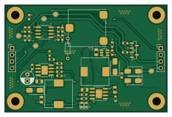
About the Power-Loss-Heat-Creep-Arrester PCB
Power-Loss-Heat-Creep-Arrester is an open source PCB design by deogratius2phantom, published on GitHub under the CC0-1.0 license. It is a 2-layer board measuring 62 × 41 mm, with 48 components from 28 distinct parts.
Other key parts include the LM393, MT3608, TP4056-42-ESOP8 and MP1584EN. By type, the board carries 21 resistors, 9 capacitors, 6 diodes, 4 ICs, 3 connectors and 2 transistors.
It belongs with the power & battery designs in this gallery.
From the project
This repository contains the Shecmatic and PCB design for a timer circucit providing 24v backup power to a 3d printer hotend fan in the even tof power loss during printing. This is aimed to reduce the chances of heat creep that can cause filament tp swell in the heatsink passage and cause clogs and jams inadvently
A KiCad PCB design for a timer circuit that provides 24 V backup power to a 3D printer hotend fan in the event of a power loss during printing. This prevents heat creep — the condition where residual heat travels up into the heatsink passage, causing filament to swell, clog, or jam.
When a 3D printer loses power mid-print, the hotend heater turns off but residual heat remains in the heater block. Without the cooling fan running, this heat can creep up the cold zone, softening and swelling the filament inside the heatsink passage. The result is a jam that requires manual disassembly to clear.
Main components on the Power-Loss-Heat-Creep-Arrester
Power-Loss-Heat-Creep-Arrester bill of materials (BOM)
48 components, 28 distinct parts — part numbers from the project's BOM.
| Qty | Part | Footprint | Refs |
|---|---|---|---|
| 1 | LM393 | SOIC-8_3.9x4.9mm_P1.27mm | U1 |
| 1 | MT3608 | SOT-23-6 | U2 |
| 1 | TP4056-42-ESOP8 | SOIC-8-1EP_3.9x4.9mm_P1.27mm_EP2.41x3.3mm_ThermalVias | U3 |
| 1 | MP1584EN | SOIC127P600X170-9N | U5 |
| 2 | BSS138 | SOT-23 | Q1, Q2 |
| 1 | CONN_01X04_SOCKET Conn_01x04_Socket | PinHeader_1x04_P2.54mm_Vertical | J1 |
| 1 | BC3550Y0302A | AMPHENOL_BC3550Y0302A | J2 |
| 1 | CONN_01X04_PIN Conn_01x04_Pin | PinHeader_1x04_P2.54mm_Vertical | J3 |
| 1 | 10K | Potentiometer_ACP_CA14-VSMD_Vertical | RV1 |
| 4 | D | D_SMA | D1, D4, D5, D6 |
| 2 | LED | LED_0603_1608Metric | D2, D3 |
| 2 | 22UH 22uH | L_10.4x10.4_H4.8 | L1, L2 |
| 2 | 22UF 22uF | C_0805_2012Metric | C1, C9 |
| 2 | 22UF 22uF | C_0603_1608Metric | C2, C11 |
| 2 | 10UF 10uF | C_0805_2012Metric | C3, C4 |
| 1 | 1UF 1uF | C_0805_2012Metric | C5 |
| 1 | 100UF 100uF | CP_Radial_D5.0mm_P2.50mm | C7 |
| 1 | 150PF 150pF | C_0603_1608Metric | C12 |
| 8 | 10K 10k | R_0603_1608Metric | R1, R2, R3, R4, R7, R8, R10, R11 |
| 1 | 4.7K 4.7k | R_0603_1608Metric | R5 |
Show 8 more
| Qty | Part | Footprint | Refs |
|---|---|---|---|
| 4 | 1k | R_0603_1608Metric | R6, R9, R13, R14 |
| 1 | 1.4K 1.4k | R_0603_1608Metric | R12 |
| 1 | 210K 210k | R_0603_1608Metric | R15 |
| 1 | 40.2K 40.2k | R_0603_1608Metric | R16 |
| 1 | 1M | R_0603_1608Metric | R17 |
| 2 | 100K 100k | R_0603_1608Metric | R18, R20 |
| 1 | 24.9K 24.9k | R_0603_1608Metric | R19 |
| 1 | 200K 200k | R_0603_1608Metric | R21 |
Power-Loss-Heat-Creep-Arrester design files
The KiCad project lives in the deogratius2phantom/Power-Loss-Heat-Creep-Arrester repository on GitHub; these links point at the commit this page was built from.
Power-Loss-Heat-Creep-Arrester: common questions
How big is the Power-Loss-Heat-Creep-Arrester PCB?
The Power-Loss-Heat-Creep-Arrester measures 62 × 41 mm, has 2 copper layers and is 1.6 mm thick.
How many components are on the Power-Loss-Heat-Creep-Arrester?
48 components, from 28 distinct parts, with part numbers taken from the project's own BOM. The full bill of materials is listed on this page.
Where can I download the Power-Loss-Heat-Creep-Arrester design files?
From the deogratius2phantom/Power-Loss-Heat-Creep-Arrester repository on GitHub, which has the KiCad layout, the schematic and the BOM; the links under Design files point to each one.
Can I use the Power-Loss-Heat-Creep-Arrester design in my own project?
Yes, under the terms of its CC0-1.0 license, which deogratius2phantom chose for the repository.
Similar boards

Stack chan
stack-chan
50 × 50 mm33 parts2LApache-2.01.7k
Display Carrier
AxxAxx
35.6 × 58.2 mm5 parts2LGPL-3.01.7k
ControllerCurrentShuntAddOn
stuartpittaway
26 × 16.9 mm9 parts2LCC-BY-NC-4.01.1k
Module 16S PassiveBalanceAddOn
61 × 74 mm86 parts2LCC-BY-NC-4.01.1k
TemperaturePCB PANEL
116 × 75.5 mm178 parts2LCC-BY-NC-4.01.1k
ProgrammingAdapter
10.5 × 83 mm3 parts2LCC-BY-NC-4.01.1k