
IMU-RC Car Board

About the IMU-RC Car Board
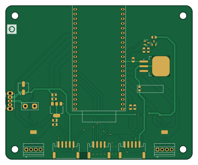
IMU-RC Car Board is an open source ESP32 PCB design by DimitriOnLSD, published on GitHub under the MIT license. It is a 2-layer board measuring 100 × 82.3 mm, with 35 components from 26 distinct parts.
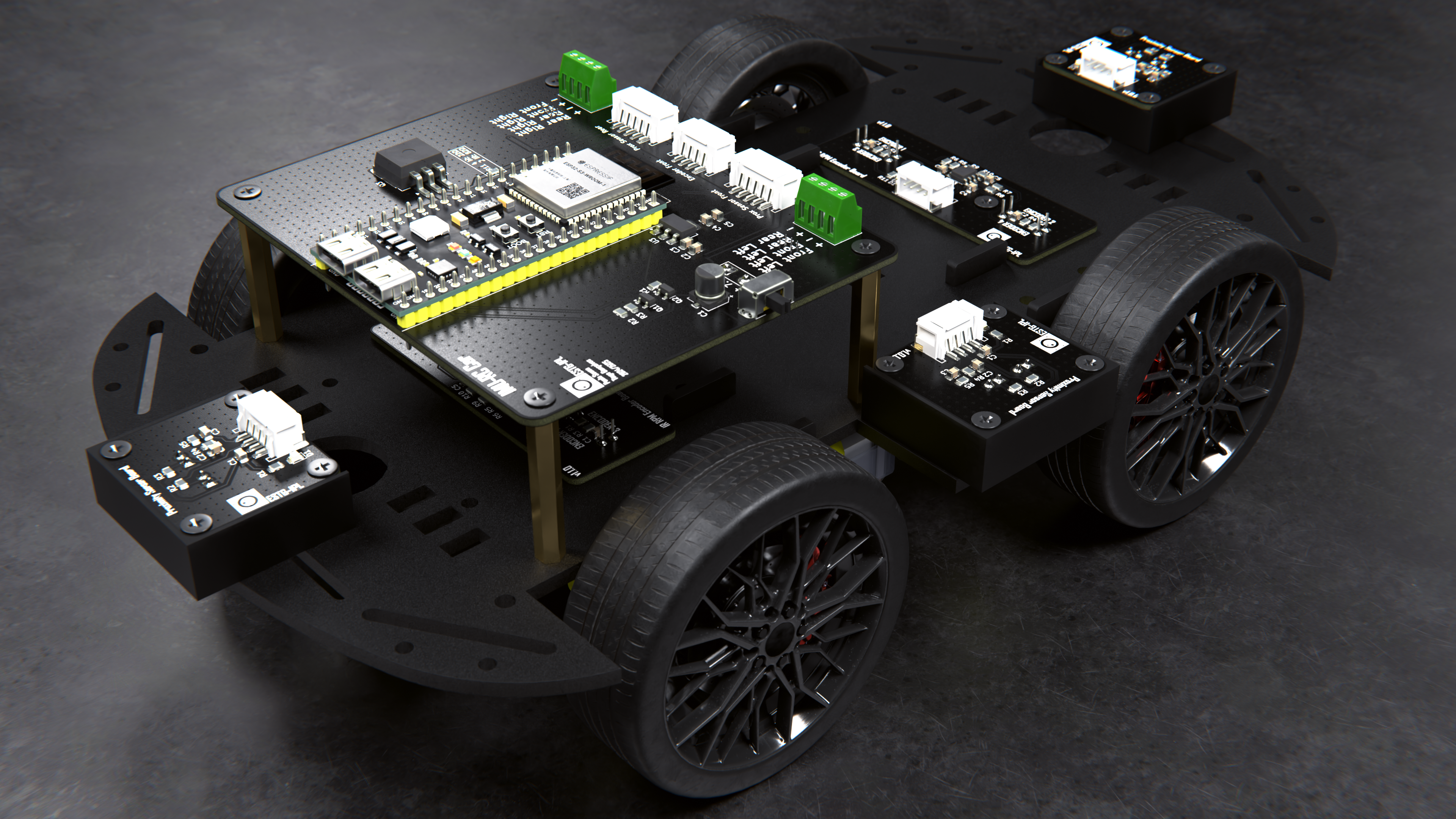
Its main chip is the ESP32-S3-DevKitC, from the ESP32 family. Other key parts include the AMS1117-3.3 and DRV8833PWP. By type, the board carries 13 capacitors, 9 connectors, 5 resistors, 4 ICs, 3 transistors and 1 switch.
It belongs with the power & battery, sensors and displays & leds designs in this gallery.
From the project
Gesture-based RC car controller using ESP32-S3, BLE, LSM6DSO IMU, OLED display, and LiPo battery with USB-C charging.
- ESP32-S3 WROOM module on a custom PCB designed in KiCad. - LSM6DSO IMU sensor for motion detection. - BLE communication using a client/server protocol with the RC car. - OLED screen (128x32) for menu options, diagnostics, and sensitivity adjustments. - Four buttons for navigation: Back, Up, Select, Down. - RGB LED to display battery or communication status. - Battery Management System (BMS) with BQ297 and MCP73831 to charge a 3.7V 250mAh LiPo battery via USB-C. - BOOT and RESET buttons for easy firmware handling.
Main components on the IMU-RC Car Board
IMU-RC Car Board bill of materials (BOM)
35 components, 26 distinct parts.
| Qty | Part | Footprint | Refs |
|---|---|---|---|
| 1 | ESP32-S3-DevKitC | ESP32-S3-DevKitC | U1 |
| 1 | AMS1117-3.3 | SOT-223-3_TabPin2 | U3 |
| 2 | DRV8833PWP | HTSSOP-16-1EP_4.4x5mm_P0.65mm_EP3.4x5mm_Mask2.46x2.31mm_ThermalVias | U6, U7 |
| 1 | IRLML6344TRPBF | SOT-23 | Q1 |
| 1 | DMP3160L-7 | SOT-23 | Q2 |
| 1 | IRLZ34N | TO-263-3_TabPin2 | Q3 |
| 1 | LiPo Battery | TerminalBlock_MaiXu_MX126-5.0-02P_1x02_P5.00mm | J1 |
| 1 | Left Terminal | TerminalBlock_Xinya_XY308-2.54-4P_1x04_P2.54mm_Horizontal | J2 |
| 1 | Right Terminal | TerminalBlock_Xinya_XY308-2.54-4P_1x04_P2.54mm_Horizontal | J3 |
| 1 | Prox Sensor FS | JST_PH_S5B-PH-SM4-TB_1x05-1MP_P2.00mm_Horizontal | J4 |
| 1 | Prox Sensor LS | JST_PH_S5B-PH-SM4-TB_1x05-1MP_P2.00mm_Horizontal | J5 |
| 1 | Prox Sensor RS | JST_PH_S5B-PH-SM4-TB_1x05-1MP_P2.00mm_Horizontal | J6 |
| 1 | Prox Sensor BS | JST_PH_S5B-PH-SM4-TB_1x05-1MP_P2.00mm_Horizontal | J7 |
| 1 | Encoder F | JST_PH_S4B-PH-SM4-TB_1x04-1MP_P2.00mm_Horizontal | J8 |
| 1 | Encoder B | JST_PH_S4B-PH-SM4-TB_1x04-1MP_P2.00mm_Horizontal | J9 |
| 1 | SW_Nidec_CAS-120A1 | SW_Slide_SPDT_Angled_CK_OS102011MA1Q | SW1 |
| 1 | 10uF | CP_Elec_5x5.7 | C1 |
| 5 | 10uF | C_0805_2012Metric | C2, C4, C6, C10, C13 |
| 3 | 100nF | C_0805_2012Metric | C3, C5, C7 |
| 2 | 10nF | C_0805_2012Metric | C8, C11 |
Show 6 more
| Qty | Part | Footprint | Refs |
|---|---|---|---|
| 2 | 2u2F | C_0805_2012Metric | C9, C12 |
| 1 | 10k | R_0805_2012Metric | R1 |
| 1 | 51k (1%) | R_0805_2012Metric | R2 |
| 1 | 33k (1%) | R_0805_2012Metric | R3 |
| 1 | 100k | R_0805_2012Metric | R4 |
| 1 | 22 (1%) | R_0805_2012Metric | R11 |
IMU-RC Car Board design files
The KiCad project lives in the DimitriOnLSD/imu-rc repository on GitHub; these links point at the commit this page was built from.
IMU-RC Car Board: common questions
What microcontroller does the IMU-RC Car Board use?
The IMU-RC Car Board is built around the ESP32-S3-DevKitC, from the ESP32 family.
How big is the IMU-RC Car Board?
The IMU-RC Car Board measures 100 × 82.3 mm, has 2 copper layers and is 1.6 mm thick.
How many components are on the IMU-RC Car Board?
35 components, from 26 distinct parts. The full bill of materials is listed on this page.
Where can I download the IMU-RC Car Board design files?
From the DimitriOnLSD/imu-rc repository on GitHub, which has the KiCad layout and the schematic; the links under Design files point to each one.
Can I use the IMU-RC Car Board design in my own project?
Yes, under the terms of its MIT license, which DimitriOnLSD chose for the repository.
Can I test firmware for the IMU-RC Car Board without the hardware?
Yes. HardLabs builds a simulation of the board from its netlist and BOM, so you can run and debug ESP32 firmware against it before you order a PCB.
More boards in imu-rc
Similar boards
 ESP32
ESP32Open Book Abridged Edition
joeycastillo
85 × 115 mm65 parts2LCC-BY-SA-4.08.1k ESP32
ESP32Esp32 minimal
atopile
36.2 × 26.8 mm20 parts2LMIT4.0k ESP32
ESP32Badge
56.3 × 39 mm239 parts4LMIT4.0k ESP32
ESP32Controller
StuckAtPrototype
29 × 74 mm58 parts4LApache-2.03.8k ESP32
ESP32Racer
36 × 50.2 mm70 parts4LApache-2.03.8k ESP32
ESP32Bitaxe
skot
56.5 × 99.8 mm86 parts4LCERN-OHL-S-2.01.4k