
Mainboard

About the Mainboard PCB
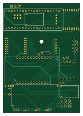
Mainboard is an open source ESP32 PCB design by DrGlaucous, published on GitHub. It is a 2-layer board measuring 70 × 100 mm, with 20 components from 17 distinct parts.
Its main chip is the ESP32-LOLIN32-Lite, from the ESP32 family. Other key parts include the RFM69HW, BP, XL60019_Boost_Module and Mini360. By type, the board carries 8 connectors, 6 ICs, 2 fuses, 2 resistors, 1 switch and 1 diode.
It belongs with the robotics & motion designs in this gallery.
From the project
Use RFM69 to transmit PPM cheaply
This is where I put everything relating to designing a small, "antweight" combat robot.
The "Transmitter" module decodes PPM signals from the controller and sends their digital values over the radio to the vehicle. There are recievers that output PPM directly without the need for the RFM middleman, but those are expensive and radio-specific. The extra range those modules would provide would be moot in the context of miniature combat robots. The analog transmitters additionally do not provide the customization abillity the digital transmiter has.
Main components on the Mainboard
Mainboard bill of materials (BOM)
20 components, 17 distinct parts — part numbers from the project's BOM.
| Qty | Part | Footprint | Refs |
|---|---|---|---|
| 1 | ESP32-LOLIN32-Lite | ESP32-LOLIN32-Lite | U1 |
| 2 | RFM69HW | HOPERF_RFM69HW | U2, U4 |
| 1 | BP | blue_pill | U3 |
| 1 | XL60019_Boost_Module | XL60019 Boost Module | U5 |
| 1 | Mini360 | Mini360 | U6 |
| 1 | Motor_A | PinHeader_1x02_P2.54mm_Vertical | J1 |
| 1 | Motor_B | PinHeader_1x02_P2.54mm_Vertical | J2 |
| 1 | Motor_C | PinHeader_1x02_P2.54mm_Vertical | J3 |
| 1 | BATT_IN | PinHeader_1x02_P2.54mm_Vertical | J4 |
| 2 | Servo | PinHeader_1x03_P2.54mm_Vertical | J5, J6 |
| 1 | ESC | PinHeader_1x03_P2.54mm_Vertical | J7 |
| 1 | ESC_PWR | PinHeader_1x02_P2.54mm_Vertical | J8 |
| 2 | Fuse 15A | PinHeader_1x02_P2.54mm_Vertical | F1, F2 |
| 1 | MAIN_CUTOFF | PinHeader_1x02_P2.54mm_Vertical | SW1 |
| 1 | 1N4007 | D_DO-41_SOD81_P7.62mm_Horizontal | D1 |
| 1 | 150k Ohm | R_Axial_DIN0207_L6.3mm_D2.5mm_P7.62mm_Horizontal | R1 |
| 1 | 10k Ohm | R_Axial_DIN0207_L6.3mm_D2.5mm_P7.62mm_Horizontal | R2 |
Mainboard design files
The KiCad project lives in the DrGlaucous/FightingRobot repository on GitHub; these links point at the commit this page was built from.
Mainboard: common questions
What microcontroller does the Mainboard use?
The Mainboard is built around the ESP32-LOLIN32-Lite, from the ESP32 family.
How big is the Mainboard PCB?
The Mainboard measures 70 × 100 mm, has 2 copper layers and is 1.6 mm thick.
How many components are on the Mainboard?
20 components, from 17 distinct parts, with part numbers taken from the project's own BOM. The full bill of materials is listed on this page.
Where can I download the Mainboard design files?
From the DrGlaucous/FightingRobot repository on GitHub, which has the KiCad layout and the BOM; the links under Design files point to each one.
Can I use the Mainboard design in my own project?
The repository has no license, so all rights stay with DrGlaucous. Use it as a reference, and ask the author before reusing the design.
Can I test firmware for the Mainboard without the hardware?
Yes. HardLabs builds a simulation of the board from its netlist and BOM, so you can run and debug ESP32 firmware against it before you order a PCB.
More boards in FightingRobot
Similar boards
 ESP32
OSO-BOOK-B1
joeycastillo
85 × 115 mm65 parts2LCC-BY-SA-4.08.1k ESP32
Powertrain
byrantech
64 × 45.4 mm171 parts4LMIT4.3k ESP32
Esp32 minimal
atopile
36.2 × 26.8 mm20 parts2LMIT4.0k ESP32
Badge
56.3 × 39 mm239 parts4LMIT4.0k ESP32
Racer
StuckAtPrototype
36 × 50.2 mm70 parts4LApache-2.03.8k ESP32
Controller
29 × 74 mm58 parts4LApache-2.03.8k