
Broadcast clock

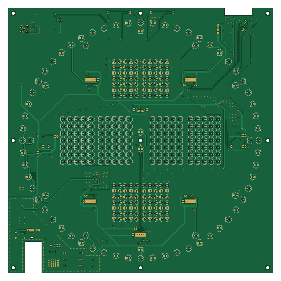
About the Broadcast clock PCB
Broadcast clock is an open source ESP32 PCB design by espena, published on GitHub under the GPL-3.0 license. It is a 4-layer board measuring 239.5 × 239.5 mm, with 440 components from 50 distinct parts.
Its main chip is the ESP32-WROVER-E, from the ESP32 family. Other key parts include the MAX6952, TLC5940PWP, LEA-M8T, NCP1117-5.0 and LM2596DS-ADJ. By type, the board carries 360 diodes, 30 capacitors, 24 resistors, 15 ICs, 3 connectors and 2 switches.
It belongs with the rf & radio and iot & wireless designs in this gallery.
From the project
Digital precision studio/broadcast masterclock with WiFi configuration, acts as local NTP server with accurate GPS time sync.
Digital precision studio/broadcast master clock with WiFi configuration, NTP client/server and GPS time sync.
You'll find a complete project description on my personal home page.
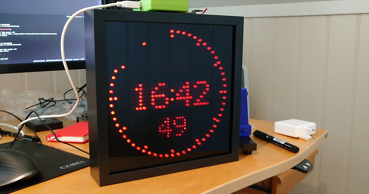
The enclosure is an 25x25 cm IKEA "Sannahed" photo frame, which is deep enough to encapsulate the circuitry. I replaced the provided plexi glass with a dark acrylic glass plate.
There are no traditional buttons to control the clock. Instead, it has a browser based web configurator. When powered on, the clock will expose a dedicated wifi network for 30 seconds. Connect to the network in order to access the clock's…
Main components on the Broadcast clock
Broadcast clock bill of materials (BOM)
440 components, 50 distinct parts — part numbers from the project's BOM.
| Qty | Part | Footprint | Refs |
|---|---|---|---|
| 2 | MAX6952 | SSOP-36_7.5x12.5mm_P0.65mm | U1, U2 |
| 1 | ESP32-WROVER-E | ESP32-WROVER-B | U3 |
| 5 | TLC5940PWP | HTSSOP-28-1EP_4.4x9.7mm_P0.65mm_EP3.4x9.5mm_Mask2.4x6.17mm_ThermalVias | U4, U5, U6, U7, U8 |
| 1 | LEA-M8T | ublox_LEA | U9 |
| 1 | NCP1117-5.0 | SOT-223-3_TabPin2 | U10 |
| 1 | LM2596DS-ADJ | NCP5663DSADJR4G | U11 |
| 3 | NCP1117-3.3 | SOT-223-3_TabPin2 | U12, U13, U14 |
| 1 | VEML7700 | VEML7700 | U15 |
| 1 | UART MCU | Magnetic-Pogo-Female-MG0425FB_1x4_P2.54mm | J1 |
| 1 | POWER | BarrelJack_DC044_Horizontal | J2 |
| 1 | UART GPS | PinHeader_1x06_P1.27mm_Vertical | J3 |
| 1 | Active GPS antenna 3.3V | SMA_Amphenol_132291-12_Vertical | AE1 |
| 1 | CR 2032 | BatteryHolder_Keystone_1058_1x2032 | BT1 |
| 1 | Buzzer | TP094003_Transducer_9x9mm | BZ1 |
| 1 | 250mA | FuseHolder_Keystone_3554 | F1 |
| 1 | BOOT | SW_SPST_TL3301_6x6mm_H4.3mm | SW1 |
| 1 | RESET | SW_SPST_TL3301_6x6mm_H4.3mm | SW2 |
| 214 | 620NM 620nm | LED_D5.0mm_p2.54 | D1, D2, D3, D4, D5, D6, D7, D8 +206 |
| 140 | 620NM 620nm | LED_D3.0mm_p2.28 | D213, D214, D215, D216, D217, D218, D219, D220 +132 |
| 1 | SK33 | D_SMA | D355 |
Show 30 more
| Qty | Part | Footprint | Refs |
|---|---|---|---|
| 1 | CMS04 | SODFL4724X108N | D356 |
| 1 | 470NM 470nm | LED_0805_2012Metric | D357 |
| 1 | 570NM 570nm | LED_0805_2012Metric | D358 |
| 1 | 590NM 590nm | LED_0805_2012Metric | D359 |
| 1 | 620NM 620nm | LED_0805_2012Metric | D360 |
| 1 | 37UH 37uH | L_Pulse_LCI-44 | L1 |
| 1 | 27NH 27nH | L_Coilcraft_0805CS | L2 |
| 2 | 26PF 27pF | C_0805_2012Metric | C1, C4 |
| 12 | 100NF 100nF | C_0805_2012Metric | C2, C3, C7, C8, C9, C10, C11, C20 +4 |
| 2 | 47UF 47µF | C_0805_2012Metric | C5, C6 |
| 1 | 1UF 1μF | C_0805_2012Metric | C12 |
| 1 | 47UF 47μF | C_0805_2012Metric | C13 |
| 3 | 820UF 820μF | CP_Elec_18x16.5 | C14, C19, C28 |
| 2 | 100UF 100μF | CP_Elec_8x10 | C15, C25 |
| 1 | 40NF 39nF | C_0805_2012Metric | C16 |
| 1 | 10NF 10nF | C_0805_2012Metric | C17 |
| 1 | 47PF 47pF | C_0805_2012Metric | C18 |
| 3 | 10µF | C_0805_2012Metric | C21, C24, C27 |
| 1 | 10μF | C_0805_2012Metric | C23 |
| 2 | 53.6K 53,6kΩ | R_0805_2012Metric | R1, R5 |
| 3 | 4.7K 4,7kΩ | R_0805_2012Metric | R2, R3, R13 |
| 2 | 4,7kΩ | R_0805_2012Metric | R4, R12 |
| 5 | 2kΩ | R_0805_2012Metric | R6, R7, R8, R9, R10 |
| 1 | 10kΩ | R_0805_2012Metric | R11 |
| 5 | 10K 10kΩ | R_0805_2012Metric | R14, R15, R16, R22, R213 |
| 2 | 4K7 4,7kΩ | R_0805_2012Metric | R17, R18 |
| 1 | 4K7 4,7k | R_0805_2012Metric | R19 |
| 1 | 5,6kΩ | R_0805_2012Metric | R20 |
| 1 | 1kΩ | R_0805_2012Metric | R21 |
| 1 | 10Ω | R_0805_2012Metric | R24 |
Broadcast clock design files
The KiCad project lives in the espena/broadcast-clock repository on GitHub; these links point at the commit this page was built from.
Broadcast clock: common questions
What microcontroller does the Broadcast clock use?
The Broadcast clock is built around the ESP32-WROVER-E, from the ESP32 family.
How big is the Broadcast clock PCB?
The Broadcast clock measures 239.5 × 239.5 mm, has 4 copper layers and is 1.6 mm thick.
How many components are on the Broadcast clock?
440 components, from 50 distinct parts, with part numbers taken from the project's own BOM. The full bill of materials is listed on this page.
Where can I download the Broadcast clock design files?
From the espena/broadcast-clock repository on GitHub, which has the KiCad layout, the schematic and the BOM; the links under Design files point to each one.
Can I use the Broadcast clock design in my own project?
Yes, under the terms of its GPL-3.0 license, which espena chose for the repository.
Can I test firmware for the Broadcast clock without the hardware?
Yes. HardLabs builds a simulation of the board from its netlist and BOM, so you can run and debug ESP32 firmware against it before you order a PCB.
Similar boards
 ESP32
ESP32Open Book Abridged Edition
joeycastillo
85 × 115 mm65 parts2LCC-BY-SA-4.08.1k ESP32
ESP32Badge
atopile
56.3 × 39 mm239 parts4LMIT4.0k ESP32
ESP32Esp32 minimal
36.2 × 26.8 mm20 parts2LMIT4.0k ESP32
ESP32Racer
StuckAtPrototype
36 × 50.2 mm70 parts4LApache-2.03.8k ESP32
ESP32Controller
29 × 74 mm58 parts4LApache-2.03.8k ESP32
ESP32Bitaxe
skot
56.5 × 99.8 mm86 parts4LCERN-OHL-S-2.01.4k