
Booster-Link

About the Booster-Link PCB
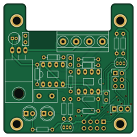
Booster-Link is an open source PCB design by GBert, published on GitHub. It is a 2-layer board measuring 50 × 50 mm, with 28 components from 23 distinct parts.
Other key parts include the 7805, 6N137 and TLC555CP. By type, the board carries 10 resistors, 5 capacitors, 4 connectors, 4 diodes, 3 ICs and 2 transistors.
From the project
miscellaneous stuff / unsorted
Einfacher Gleisboxbooster =========================
Optionen: - ohne öffnen der Gleisbox - automatishce Gleisspannungsabschaltung (Stopp) nach 250ms - direkte Anbindung an die Gleisbox (nur zwei Widerstände + Transistor)
BOM (über interne Signale der Gleisbox) --------------------------------------- |Reference | Value | Footprint | |---------------|---------------|---------------| |Q21 |BC337 |TO-92 | |R21 |1k5 Ohm |0207 | |R22 |390 Ohm |0207 |
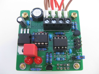
Main components on the Booster-Link
Booster-Link bill of materials (BOM)
28 components, 23 distinct parts — part numbers from the project's BOM.
| Qty | Part | Footprint | Refs |
|---|---|---|---|
| 1 | 7805 | TO-220-78xx | U1 |
| 1 | 6N137 | dil_8-300_socket | U2 |
| 1 | TLC555CP | dil_8-300_socket | U11 |
| 2 | BC337 | TO-92_Inline_Narrow_Oval | Q1, Q21 |
| 1 | Conn_01x04 | akl0711,5-4 | P1 |
| 1 | IBT-2 | Socket_Strip_Straight_2x04 | P2 |
| 1 | EXTCON | Pin_Header_Straight_2x03 | P3 |
| 1 | CONN_01X03 | Pin_Header_Straight_1x03 | P4 |
| 2 | 1N4148 | diode_do35 | D1, D11 |
| 2 | Led_Small | LED-5MM | D2, D3 |
| 2 | 100NF 100nF | cnp_3mm_disc | C1, C11 |
| 1 | 10uF | CP_4x5mm | C2 |
| 1 | 18PF 100nF | cnp_3mm_disc | C3 |
| 1 | 100NF 2.2uF | C_Disc_D9.0mm_W5.0mm_P5.00mm | C12 |
| 1 | 10K 1k5 | RC03 | R1 |
| 1 | 680 390 | RC03 | R2 |
| 2 | 680 1k5 | RC03 | R3, R5 |
| 1 | 4K7 390 | RC03 | R4 |
| 1 | 3K3 1k5 | RC03 | R7 |
| 1 | 120 100k | RC03 | R11 |
Show 3 more
| Qty | Part | Footprint | Refs |
|---|---|---|---|
| 1 | 270 100k | RC03 | R12 |
| 1 | 120 1k5 | RC03 | R21 |
| 1 | 3K3 390 | RC03 | R22 |
Booster-Link design files
The KiCad project lives in the GBert/misc repository on GitHub; these links point at the commit this page was built from.
Booster-Link: common questions
How big is the Booster-Link PCB?
The Booster-Link measures 50 × 50 mm, has 2 copper layers and is 1.6 mm thick.
How many components are on the Booster-Link?
28 components, from 23 distinct parts, with part numbers taken from the project's own BOM. The full bill of materials is listed on this page.
Where can I download the Booster-Link design files?
From the GBert/misc repository on GitHub, which has the KiCad layout and the BOM; the links under Design files point to each one.
Can I use the Booster-Link design in my own project?
The repository has no license, so all rights stay with GBert. Use it as a reference, and ask the author before reusing the design.
More boards in misc
 PIC
PICCANBuster
100 × 100 mm177 parts2LNo license99 PIC
PICAll in One Railroad Interface
85 × 56.5 mm151 parts2LNo license99 PIC
PICBPi-CAN
100 × 100 mm146 parts2LNo license99
BPI-AddOn
100 × 100 mm94 parts2LNo license99 PIC
PICMfx link2
50 × 50 mm61 parts2LNo license99 PIC
PICDsPIC33-Arduino
68.6 × 53.3 mm60 parts2LNo license99 PIC
PICSmallest Rocrail Server Ever II
82 × 72 mm58 parts2LNo license99 PIC
PICMfx link
50 × 50 mm53 parts2LNo license99
RPi-MCP2515
65 × 56.5 mm42 parts2LNo license99 PIC
PICRPi-MCP2517
65 × 56.5 mm35 parts2LNo license99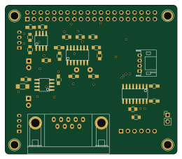 PIC
PICRPi-Rail
65 × 56.5 mm35 parts2LNo license99